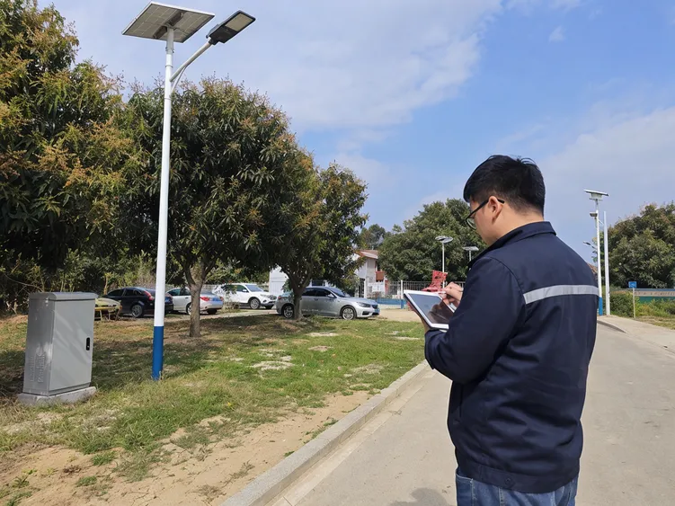
Smart Solar Lighting System | JXSOL
A complete, configured smart solar lighting system — solar panel, battery, LED module, controller, sensor logic, and optional IoT communication — matched as one system before production.
Built for project contractors, distributors, and OEM buyers who need a supplier that sizes the battery and panel to the installation site, not to a catalog default. Standard models from 100 units.
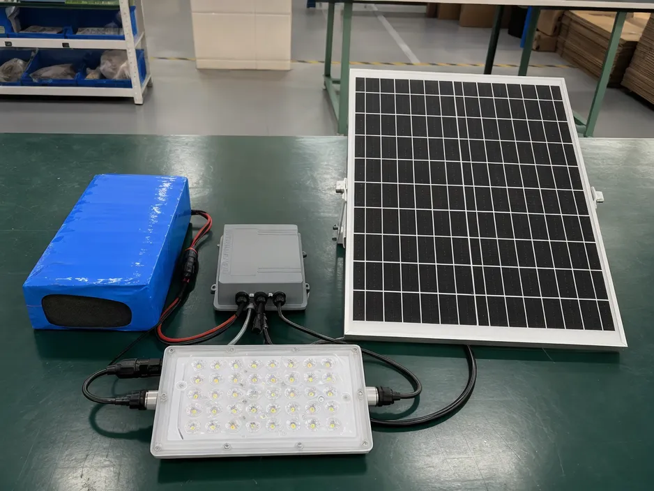
Smart Solar Lighting System for Configured Project Orders
A smart solar lighting system is a configured product, not a collection of parts. The solar panel, LiFePO4 battery pack, LED module, programmable controller, sensor, mounting structure, and — where specified — IoT communication module all interact. Size the battery to a catalog default instead of the installation latitude and the system underperforms through winter. Pair a high-lumen LED module with an undersized panel and runtime degrades after the first cloudy week. Add a 4G communication module without accounting for its continuous power draw and the battery budget is wrong from the start.
We've been manufacturing solar-powered outdoor lighting since 2012. The smart solar lighting category is where the engineering complexity is highest, and it's where we see the most field failures from buyers who sourced components separately or accepted a standard configuration without site-specific sizing.
This page covers the complete smart solar lighting system — the core product in our smart solar lighting systems category — for buyers who need a configured, quotation-ready system for resale, project deployment, or OEM programs.
What a Configured System Includes
-
Solar Panel
Wattage sized to winter solstice irradiance at target latitude — not annual average
-
LiFePO4 Battery Pack
Capacity driven by LED draw, operating hours, dimming schedule, and autonomy nights
-
LED Module
Power and optic selection back-calculated from lux target at road surface
-
Programmable Controller
Firmware pre-programmed to dimming schedule; lockable for consistent field behavior
-
Sensor
PIR or microwave, selected to application environment and climate
-
IoT Communication Module (Optional)
4G, NB-IoT, Zigbee, or LoRa — power draw factored into battery budget at specification stage
Where Field Failures Come From
The most common source of field failures we see: buyers who sourced components separately or accepted a standard configuration without site-specific sizing. By the time the container ships, the battery capacity, panel wattage, controller firmware, and sensor logic are fixed. If they're wrong for the site, you're managing warranty claims on the next order — not reorders.
Configuration Variables That Decide Runtime Before Production
The most expensive mistake in smart solar lighting procurement is treating configuration as a post-order detail. By the time the container ships, the battery capacity, panel wattage, controller firmware, and sensor logic are fixed. If they're wrong for the site, you're managing warranty claims and field adjustments on the next order — not reorders.
Here are the variables that must be resolved before production, and what each one means for your order.
Installation Latitude & Seasonal Irradiance
Battery capacity and solar panel wattage are both calculated from the installation latitude. A panel sized to annual average irradiance will underperform from October through March in temperate markets — the battery never fully recovers on short winter days, and runtime degrades progressively over consecutive cloudy days.
We size panels to the winter solstice irradiance at the target latitude, not the annual average. In practice, this adds 15–25% to the panel wattage for buyers in Northern Europe, Canada, or high-altitude markets.
Middle East / SE Asia / Sub-Saharan Africa: Irradiance is high enough year-round that the sizing difference is smaller — but operating temperature range affects battery chemistry selection.
LED Power & Target Lux Level
LED power drives battery draw, which drives battery capacity, which drives panel wattage. The chain runs in one direction. If your project spec calls for a specific lux level at road surface — a common requirement in municipal tenders — we work backward from the lux target to the LED power and optic selection, then size the battery and panel from there.
Watch out: Buyers who specify LED wattage without a lux target sometimes end up with a system that meets the wattage spec but fails the photometric requirement.
Operating Hours & Dimming Schedule
A system running 100% output for 10 hours per night draws significantly more battery capacity than one running a standard dimming profile:
- 100% for the first 2–3 hours after dusk
- 40–50% mid-night
- Motion-triggered return to 100%
- Off before dawn
The dimming schedule is programmed into the controller before shipment. For large installations, we can lock firmware to prevent field modification — ensuring consistent system behavior across the deployment.
Autonomy Nights (Consecutive Cloudy Days)
Autonomy nights define how many consecutive days without meaningful solar input the system must sustain full or reduced operation. This is the single biggest driver of battery capacity — and the variable most often underspecified by buyers who haven't operated in the target climate.
Standard configurations are typically sized for 3–5 autonomy nights. Buyers in Northern Europe, the Pacific Northwest, or monsoon-affected markets often require 5–7 nights. Specifying fewer autonomy nights than the climate demands is the most common cause of winter performance complaints.
Rule of thumb: Each additional autonomy night adds roughly 15–20% to battery capacity and a proportional increase to system cost. It's a tradeoff worth quantifying before production.
Operating Temperature Range
Battery chemistry selection depends on the minimum operating temperature at the installation site. Standard LiFePO4 cells perform well down to around −10°C. Below that, capacity degrades significantly and charge acceptance drops — meaning the panel charges the battery less efficiently on cold mornings.
For installations in climates that regularly reach −20°C or below, we specify low-temperature LiFePO4 cells with a built-in heating circuit. This adds cost and draws a small amount of battery capacity, both of which are factored into the sizing model.
High-heat markets: Sustained ambient temperatures above 40°C accelerate battery degradation. We derate capacity and adjust cycle life projections accordingly for Middle East and desert deployments.
Sensor Type & Control Logic
PIR sensors are cost-effective and reliable in most environments but can false-trigger in high-wind conditions or when foliage is nearby. Microwave sensors penetrate non-metallic enclosures and perform better in extreme cold, but draw slightly more power and require careful sensitivity calibration to avoid false triggers from rain or insects.
Control logic decisions that must be made before production:
- Motion hold time (how long the light stays at 100% after motion clears)
- Dim level when no motion is detected
- Time-based override windows (e.g., full output during peak pedestrian hours)
- Low-battery protection threshold (minimum SOC before the system dims to preserve battery life)
What We Need From You Before We Size the System
When buyers come to us with a project, we ask for six data points before we produce a specification. If any of these are unknown, we'll tell you what assumption we're making and what the risk is if that assumption is wrong.
Installation country and latitude (or GPS coordinates)
Required lux level at road or ground surface, or LED wattage if lux is not specified
Required operating hours per night and preferred dimming profile
Minimum and maximum ambient temperature at the site
Required autonomy nights (or local climate data if unknown)
IoT or remote monitoring requirements, if any
All-in-One vs Split Systems: Which Architecture Fits Your Project
The two dominant form factors in solar street lighting serve different project profiles. Understanding the tradeoffs before you specify saves significant rework downstream.
| Factor | All-in-One | Split System |
|---|---|---|
| Installation | Single unit mounts to pole arm; no wiring between components | Panel mounts separately; wiring run down pole to battery box |
| Panel Size Limit | Constrained by head unit dimensions; typically up to ~100W | Panel can be sized independently; supports higher wattage |
| Battery Location | Integrated into head unit; exposed to ambient temperature swings | Ground-level box; easier to insulate and service |
| Wind Load | Higher wind load at head; pole and foundation must be sized accordingly | Panel can be angled or positioned to reduce wind exposure |
| Maintenance | Requires lift or ladder to access battery; higher service cost | Battery accessible at ground level; faster field service |
| Aesthetics | Clean, integrated appearance; preferred for urban and commercial sites | More visible components; better suited to industrial or rural sites |
| Best Fit | Urban roads, parking lots, commercial properties, lower-latitude markets | High-latitude markets, large battery requirements, industrial sites |
When All-in-One Makes Sense
- Installation latitude below 45°N/S — sufficient irradiance to keep panel size within head unit constraints
- Urban or commercial sites where aesthetics and installation speed matter
- Projects with limited installation crew skill — single-unit mounting reduces wiring errors
- Ambient temperature range stays within −10°C to +45°C — battery chemistry performs within spec
When Split Systems Are the Right Call
- High-latitude markets where winter sizing requires panel wattage beyond all-in-one limits
- Extreme cold climates where ground-level battery insulation meaningfully extends battery life
- High-wind zones where reducing head unit wind load is a structural requirement
- Large deployments where battery serviceability at ground level reduces long-term maintenance cost
IP Rating, IK Rating, and What the Numbers Actually Mean
Protection ratings appear on every spec sheet, but the numbers are frequently misread or misapplied. Here's what each rating covers, what it doesn't, and what to specify for different deployment environments.
IP Rating (Ingress Protection)
The IP code has two digits. The first covers solid particle ingress (dust); the second covers liquid ingress (water). A missing digit is replaced with X, meaning untested — not protected.
IP6X = fully dust-tight. No ingress of dust under any conditions. This is the minimum you should accept for outdoor luminaires in any environment.
IPX5 = protected against water jets from any direction. Adequate for most outdoor applications with normal rainfall.
IPX6 = protected against powerful water jets. Required for coastal sites, high-rainfall climates, or installations subject to pressure washing.
IPX7 = protected against temporary immersion up to 1m for 30 minutes. Relevant for flood-prone installations or ground-level battery boxes in high-rainfall areas.
Common misread: IP65 is not "better" than IP67 in all respects. IP67 covers immersion but is not automatically tested against sustained water jets. For most street lighting, IP66 is the practical standard — dust-tight and resistant to powerful water jets without requiring immersion protection.
IK Rating (Impact Protection)
The IK code rates resistance to mechanical impact, expressed in joules of energy. It's a separate standard from IP and is frequently omitted from spec sheets — which means the product hasn't been tested, not that it's protected.
| Rating | Impact Energy | Equivalent | Typical Use |
|---|---|---|---|
| IK06 | 1 J | Small thrown object | Low-risk residential |
| IK08 | 5 J | Moderate impact | Standard commercial |
| IK09 | 10 J | Heavy impact | Public roads, parks |
| IK10 | 20 J | Sledgehammer-level | High-vandalism, industrial |
What to Specify by Environment
- Municipal roads and public parks: IP66 + IK09 minimum
- High-vandalism urban areas: IP66 + IK10
- Coastal or high-humidity sites: IP67 + IK08 minimum; consider marine-grade housing
- Private commercialor industrial sites: IP65 + IK08 typically sufficient
Spec sheet gap: Many manufacturers list IP rating prominently and omit IK entirely. If IK is absent, ask for it explicitly. A luminaire with no IK rating has not been tested — and in public environments, that's a procurement risk.
Beyond IP and IK: Corrosion Resistance and Housing Materials
IP and IK ratings don't cover corrosion. A luminaire can be IP66-rated and still fail within two years in a coastal environment if the housing alloy or surface treatment isn't specified correctly.
Die-Cast Aluminum
Standard for most solar street lights. Lightweight, good thermal conductivity for heat dissipation. Adequate for inland and low-humidity environments.
Limitation: Requires powder coat or anodizing for coastal use. Bare aluminum corrodes in salt-laden air within 12–24 months.
Powder-Coated Aluminum
Adds a protective polymer layer. Extends corrosion resistance significantly. Specify minimum 60–80 micron coating thickness for coastal deployments.
Limitation: Coating integrity depends on application quality. Chips and scratches expose base metal. Inspect for coating uniformity at procurement.
Marine-Grade / Salt Spray Tested
Some manufacturers test to ASTM B117 or equivalent salt spray standards (500–1000 hours). This is the relevant spec for coastal, port, and offshore installations.
Ask for: Salt spray test hours, test standard referenced, and whether the full assembly (not just housing) was tested.
Operating Temperature Range
Temperature range is listed on most spec sheets but rarely scrutinized. The relevant figure is the battery operating range, not the LED or controller range — batteries are almost always the limiting component.
For cold-climate deployments below −10°C, verify that the BMS includes low-temperature charge protection and that the spec sheet lists actual tested discharge capacity at minimum operating temperature — not just a nominal range.
Pole Height, Arm Length, and Mounting Considerations
Pole height and arm geometry directly affect illuminance distribution, uniformity, and the structural loads the system must handle. Getting these wrong means either under-lit roads or over-engineered poles — both are costly.
Pole Height by Application
Mounting height determines the illuminated area per fixture and the required lumen output. Higher poles cover more area but require more lumens to maintain the same illuminance level — the relationship is roughly inverse-square.
Lower mounting keeps light on the path surface. Spacing typically 15–25 m. Lumen requirement relatively modest — 2,000–5,000 lm depending on path width.
Standard residential mounting range. Spacing 25–35 m single-side or staggered. Typical lumen range 5,000–10,000 lm.
Wider roads require higher mounting for adequate spread. Spacing 30–40 m. Lumen requirement 10,000–18,000 lm. Solar feasibility depends heavily on available irradiance.
High-mast applications. Solar becomes marginal at this scale — panel area and battery capacity requirements are large. Dual-panel split systems are sometimes used.
Arm Length, Tilt, and Panel Orientation
The arm positions the luminaire over the road surface. Arm length affects overhang, which shifts the illuminance pattern relative to the pole. Panel tilt and azimuth affect energy yield independently of luminaire position.
Arm Length Considerations
- Standard arm lengths run 0.5–2.5 m. Longer arms increase bending moment at the pole — structural calculations must account for combined wind load on panel and luminaire.
- For all-in-one units, the arm is fixed. For split systems, arm and panel mount are independent — panel can face south while arm extends over the road.
- Median-mounted poles (dual-arm) require symmetric load calculations. Panel placement on median poles is constrained by shading from the opposite arm.
Panel Tilt Angle
- Optimal fixed tilt is approximately equal to site latitude for year-round energy yield. Steeper tilt favors winter; shallower tilt favors summer.
- All-in-one panels are typically fixed at 5–15° — optimized for low-latitude markets. At latitudes above 40°, this is a meaningful energy yield penalty.
- Adjustable tilt brackets (common on split systems) allow field optimization. Specify the tilt range and locking mechanism — vibration can shift tilt over time on poorly designed brackets.
North-south road orientation: When roads run north-south, poles on the east side have panels facing west and vice versa. This is a common installation scenario that reduces yield by 15–25% compared to south-facing panels. Account for this in energy calculations — don't assume south-facing yield for all poles in a project.
Wind Load and Structural Specification
Solar panels add significant wind-exposed area to a pole. A 100W monocrystalline panel is roughly 0.6 m² of projected area. At 40 m/s wind speed, that's a substantial lateral force — and it acts at the top of the pole, maximizing bending moment at the base.
What to Verify in the Structural Spec
- Design wind speed (m/s or mph) — must match local wind zone classification, not a generic "suitable for high wind" claim
- Panel area included in wind load calculation — some manufacturers calculate pole strength without accounting for panel area
- Foundation specification — anchor bolt pattern, embedment depth, and concrete grade must be matched to pole and wind load
- Wall thickness and alloy grade of the pole shaft — not just outer diameter
Common Structural Failures
- Pole rated for luminaire wind load only — panel area not included in calculation. Panel acts as a sail and exceeds design load in first major storm.
- Anchor bolts undersized for actual soil conditions. Manufacturer provides generic foundation spec; installer uses it without site-specific geotechnical review.
- Thin-wall poles with adequate outer diameter but insufficient wall thickness. Passes visual inspection but fails under combined bending and torsion loads.
Light Distribution, Optics, and Photometric Design
Lumen output is only half the story. How those lumens are distributed across the road surface determines whether the installation meets photometric standards — and whether it wastes energy on sky glow and spill light.
IES Distribution Types
The IES (Illuminating Engineering Society) classifies road luminaire distributions by lateral spread and longitudinal throw. Specifying the correct type for road width and pole spacing is a basic photometric design step that's often skipped in solar street light procurement.
Lateral spread up to 2.25× mounting height. Used for narrow streets and pathways where the pole is at the road edge.
Lateral spread up to 2.75× mounting height. The most common distribution for standard road widths with side-of-road poles.
Lateral spread up to 3.75× mounting height. Used for wide arterials where the pole is at the road edge and must cover the full width.
Circular or square symmetric distribution. Used for intersections and median-mounted poles where light must spread equally in all directions.
CCT, CRI, and Practical Implications
Correlated Color Temperature and Color Rendering Index affect visibility, safety perception, and ecological impact. Both are frequently over-specified or misunderstood in procurement.
CCT: What to Specify and Why
Warm white. Minimal blue-light content — lowest ecological impact, least sky glow contribution. Suitable for residential areas and wildlife-sensitive sites. Lower perceived brightness at same lux level.
Warm-neutral. Good balance of ecological impact and visibility. Increasingly specified by municipalities replacing HPS to maintain warm appearance while improving efficiency.
Neutral white. Standard for most road lighting. Good scotopic sensitivity — human eyes perceive it as brighter at equivalent lux. Common default for solar street lights.
Cool white. High blue content. Maximizes perceived brightness per lumen but increases sky glow, ecological disruption, and glare complaints. Avoid in residential areas.
CRI for Road Lighting
CRI ≥ 70 is the minimum for road lighting under most standards. CRI ≥ 80 improves color recognition — relevant for security applications where identifying clothing or vehicle color matters. CRI above 80 offers diminishing returns for road lighting and typically increases cost.
Note: CRI is measured at a single point. R9 (saturated red rendering) is a better indicator for security and CCTV-adjacent applications — ask for R9 value separately if color accuracy matters.
Practical note: Most solar street light manufacturers default to 6000K because it appears brighter in demos and marketing photos. For actual deployments, 4000K or 3000K is almost always the better specification — lower ecological impact, fewer glare complaints, and equivalent or better mesopic visibility on roads.
Photometric Files and Lighting Simulation
Any credible solar street light manufacturer should be able to provide an IES or LDT photometric file for their luminaire. This file contains the full angular intensity distribution and is required to run accurate lighting simulations in tools like DIALux or AGi32.
What a Photometric Simulation Tells You
- Average maintained illuminance (lux) on the road surface at end of rated life
- Uniformity ratio (minimum to average lux) — critical for meeting EN 13201 or ANSI/IES RP-8 standards
- Glare rating (TI or UGR) — required for road safety compliance in most jurisdictions
- Optimal pole spacing for the specified mounting height and road width
Red Flags in Photometric Claims
- Lux values quoted without specifying mounting height, spacing, or road width — these numbers are meaningless without context
- No IES or LDT file available — simulation cannot be verified independently
- Lux values measured at ground directly below the fixture — peak nadir lux is not a useful metric for road lighting uniformity
- Simulation results based on initial lumens rather than maintained lumens — always ask for the maintenance factor applied
Battery Technology: LiFePO4 vs. Other Chemistries
The battery is the most failure-prone component in a solar street light system. Chemistry selection determines cycle life, temperature performance, safety, and total cost of ownership over a 10-year deployment.
LiFePO4
Lithium Iron Phosphate — RecommendedThe standard for quality solar street lights. Superior cycle life and thermal stability justify the higher upfront cost. A properly sized LiFePO4 pack should outlast the LED and solar panel in most deployments.
NMC / NCA
Lithium Nickel Manganese / Nickel Cobalt — CautionHigher energy density makes NMC attractive for compact all-in-one designs, but shorter cycle life and higher thermal runaway risk are significant drawbacks for outdoor, unattended installations in hot climates.
Lead-Acid / Gel
Legacy Chemistry — Avoid for New InstallationsStill found in low-cost systems. Short cycle life, high weight, and severe capacity loss in heat make lead-acid a poor choice for solar street lights. Replacement costs over a 10-year period typically exceed the initial savings.
Battery Sizing: Autonomy Days
Battery capacity must be sized to sustain full-night operation through consecutive cloudy days — the number of which depends on the installation location's climate. This is expressed as "autonomy days."
Autonomy Day Calculation
Required capacity (Wh) = Nightly load (W) × Operating hours × Autonomy days ÷ DoD limit
Example: 30W × 10h × 3 days ÷ 0.8 DoD = 1,125 Wh minimum
Typical Autonomy Targets by Climate
Common overselling tactic: Manufacturers often quote battery capacity in Wh at nominal voltage, but the usable capacity at the DoD limit they actually program into the BMS may be 20–30% lower. Always ask for usable capacity at the programmed DoD cutoff, not total rated capacity.
Battery Management System (BMS)
The BMS protects the battery pack from conditions that accelerate degradation or create safety hazards. In solar street lights, BMS quality is often the difference between a 3-year and a 7-year battery life.
Overcharge and over-discharge protection
Prevents cell voltage from exceeding safe limits in either direction — the most common cause of premature capacity loss.
Temperature-compensated charging
Adjusts charge voltage based on battery temperature. Critical in climates with large day/night temperature swings — without it, batteries are chronically overcharged in summer.
Cell balancing
Equalizes charge across individual cells in the pack. Without balancing, the weakest cell limits total capacity and degrades faster than the rest.
Short-circuit and overcurrent protection
Disconnects the pack under fault conditions. Essential for outdoor installations where wiring damage or water ingress can create fault currents.
Ask manufacturers for the BMS specification sheet separately from the battery spec. A battery with a weak BMS will underperform its rated cycle life regardless of cell quality.
Charge Controllers: MPPT vs. PWM
The charge controller sits between the solar panel and the battery, managing energy harvest and protecting the battery from improper charging. The choice between MPPT and PWM has a direct impact on system efficiency and battery longevity.
MPPT — Maximum Power Point Tracking
Recommended for systems above 50WMPPT controllers continuously adjust the electrical operating point of the solar panel to extract maximum available power regardless of battery state of charge or temperature. This is particularly valuable during partial shading, early morning, and late afternoon when the panel is not at peak output.
PWM — Pulse Width Modulation
Acceptable for small systems under 30WPWM controllers regulate charging by rapidly switching the panel connection on and off, effectively clamping the panel voltage to the battery voltage. Simpler and cheaper than MPPT, but wastes available panel power whenever the panel's maximum power point voltage exceeds the battery voltage.
Integrated vs. Separate Charge Controllers
In all-in-one solar street lights, the charge controller is integrated into the main control unit alongside the LED driver and motion sensor logic. In split systems, it may be a separate component. Each approach has tradeoffs.
Integrated Controller (All-in-One)
Separate Charge Controller (Split System)
Motion Sensors, Dimming Profiles, and Energy Management
Adaptive dimming is the primary mechanism by which solar street lights extend battery autonomy without reducing perceived safety. Understanding how dimming profiles work — and their limitations — is essential for specifying systems that perform reliably in the field.
Dimming Profile Strategies
Time-Based Dimming
Most commonThe controller dims the LED to a preset level (typically 30–50%) after a fixed time period — often midnight or 2–3 hours after sunset. Full brightness resumes at a set time before sunrise.
PIR Motion-Activated Boost
RecommendedThe light operates at a low standby level (10–30%) and boosts to full power when a PIR sensor detects movement. After a configurable hold time (typically 30–120 seconds),it returns to standby level. This is the most energy-efficient profile for low-traffic locations.
Combined Time + Motion
Best practiceFull brightness during peak hours (e.g., 6 pm–midnight), then motion-activated boost during low-traffic hours (midnight–6 am). Balances safety perception with energy conservation across the full night cycle.
Battery-State Adaptive Dimming
AdvancedThe controller monitors battery state of charge in real time and progressively reduces output power as the battery depletes. Prevents full shutdown on consecutive cloudy nights by trading brightness for extended runtime.
PIR Sensor Performance Factors
Passive infrared sensors detect changes in infrared radiation caused by moving warm bodies. Their real-world performance depends heavily on mounting height, detection angle, and environmental conditions.
Mounting Height vs. Detection Range
Higher mounting increases coverage area but reduces sensitivity to slow-moving or low-heat targets. Optimal PIR performance is typically between 4–8 m mounting height. Above 10 m, detection reliability drops for pedestrians.
Ambient Temperature Effects
PIR sensors detect contrast between body heat and background temperature. In hot climates where ambient temperature approaches body temperature (above 35°C), detection range and reliability decrease significantly. Microwave or dual-technology sensors are more reliable in these conditions.
False Triggers
Wind-blown foliage, animals, and rapid temperature changes can trigger false activations. While false triggers waste some energy, they are generally preferable to missed detections in safety-critical applications. Adjustable sensitivity and time-delay settings help reduce nuisance activations.
Detection Angle and Overlap
Most integrated PIR sensors have a detection cone of 100–120°. For pathway lighting, adjacent fixtures should be spaced so their detection zones overlap slightly, ensuring a pedestrian is detected before they enter a dark gap between lights.
Quantifying the Energy Benefit of Dimming
The energy savings from dimming directly translate to reduced battery capacity requirements — or extended autonomy with the same battery. The table below illustrates the effective nightly energy draw under different dimming profiles for a 30W LED fixture operating 11 hours per night.
| Profile | Avg. Power | Nightly Draw | vs. Full Power |
|---|---|---|---|
| Full brightness all night | 30 W | 330 Wh | — |
| Time-based dim to 40% after midnight (5 h dim) | ~22 W | ~242 Wh | −27% |
| Motion boost: 20% standby, 100% on detection (30% active time) | ~15 W | ~165 Wh | −50% |
| Combined: full 6 h, motion-boost 5 h at 15% active time | ~19 W | ~209 Wh | −37% |
Figures are illustrative estimates based on typical dimming profiles. Actual savings depend on traffic patterns, hold time settings, and LED driver efficiency at partial load.
IP Ratings, Weatherproofing, and Corrosion Resistance
Solar street lights operate outdoors continuously for years. Ingress protection ratings, material selection, and coating quality determine whether a fixture survives its intended service life or fails prematurely due to moisture, dust, or corrosion.
Understanding IP Ratings
The IP (Ingress Protection) rating system, defined by IEC 60529, uses two digits to describe protection against solid particles and liquids. For outdoor luminaires, both digits matter — and the second digit is often the more critical one.
First digit: solid particle protection
Second digit: liquid ingress protection
Minimum Ratings for Outdoor Use
The LED module and driver should be rated at minimum IP65. The battery compartment — particularly in all-in-one units — should be IP65 or higher. IP44 is insufficient for exposed outdoor installations and should be rejected regardless of price point.
Housing Materials and Corrosion Resistance
IP rating alone does not guarantee long-term weatherproofing. Seal degradation, UV-induced embrittlement, and corrosion of fasteners and housings are common failure modes that IP testing does not capture.
Die-Cast Aluminium
The standard material for quality solar street light housings. Excellent thermal conductivity (aids LED heat dissipation), good corrosion resistance when anodised or powder-coated, and high structural rigidity. Verify coating thickness — minimum 60–80 µm powder coat for coastal or humid environments.
PC / ABS Plastic Housings
Used in lower-cost all-in-one units. Lighter and cheaper than aluminium, but UV degradation causes embrittlement and cracking over 3–5 years in high-UV environments. Look for UV-stabilised grades and verify IK impact rating if vandalism is a concern.
Stainless Steel Fasteners
A frequently overlooked detail. Zinc-plated or carbon steel fasteners corrode within 1–2 years in coastal or high-humidity environments, causing housing seal failure and structural loosening. Specify A2 or A4 stainless steel fasteners for all external hardware.
Lens and Optical Cover
Tempered glass lenses maintain optical clarity over time and resist UV yellowing. Polycarbonate lenses are lighter but yellow and haze after 3–5 years, reducing lumen output by 10–20%. For long-life installations, specify tempered glass optical covers.
IK Impact Rating — Often Overlooked
The IK rating (IEC 62262) measures resistance to mechanical impact, expressed in joules. It is separate from the IP rating and is particularly relevant for fixtures in public spaces, car parks, or areas with vandalism risk.
Quotation-Ready Specification Table for System Selection
The table below covers typical product-level values for our smart solar lighting system range. These are standard configuration values — exact specifications depend on the selected model and project configuration. Contact us for detailed data sheets on specific models.
| Parameter | Typical / Standard Values |
|---|---|
| LED Power | 20W – 200W (project-configured) |
| Lumen Output | 2,000 lm – 24,000 lm |
| Efficacy | ≥160 lm/W (standard LED module) |
| Color Temperature | 2700K – 6500K; standard: 4000K, 5000K, 6000K |
| Color Rendering Index | CRI ≥70 (standard); CRI ≥80 available |
| Battery Chemistry | LiFePO4 (standard); Li-ion (available) |
| Battery Capacity | 20Ah – 200Ah (sized to project autonomy requirement) |
| Battery Cycle Life | LiFePO4: 2,000+ cycles; Li-ion: 500–800 cycles |
| Solar Panel Type | Monocrystalline silicon |
| Solar Panel Wattage | 30W – 300W (matched to battery and installation latitude) |
| Autonomy Nights | 2–7 nights (project-specific sizing) |
| Charging Controller | MPPT (standard) |
| Control Modes | Time control, PIR motion sensor, microwave sensor, dimming schedule, remote/IoT |
| Dimming Levels | Configurable: 0–100% in programmable steps |
| PIR Sensor Range | 8–12 m detection range, 120° angle |
| Microwave Sensor | Adjustable sensitivity; penetrates non-metallic materials |
| Communication Options | Standalone (no network); 4G; NB-IoT; Zigbee; LoRa |
| Ingress Protection | IP65 (standard); IP67 (available for battery compartments and connectors) |
| Operating Temperature | -20°C to +60°C |
| Housing Material | Die-cast aluminum (standard); PC lens |
| Mounting Options | Integrated all-in-one; split with separate panel; pole-top; wall bracket; arm mount |
| Pole Compatibility | Standard 60–76mm OD pole arm; custom pole diameter available |
| Certifications | ISO 9001:2015, CE, RoHS, IP65/IP67, IEC 62124 |
| Warranty | 3 years standard |
| OEM/ODM Variables | Lumen output, CCT, battery capacity, panel wattage, sensor logic, firmware, housing color, branding, packaging |
Specifications shown are standard configuration values for this product range. Actual specifications depend on project configuration and selected model. Contact us for detailed product data sheets and project-specific sizing.
All-in-One or Split System: Landed Cost, Output, and Service Trade-Offs
The choice between an all-in-one and a split smart solar lighting system is a commercial decision as much as a technical one. Both configurations use the same core components — solar panel, battery, LED module, controller, sensor — but the physical arrangement affects freight cost, installation time, output ceiling, battery service access, and which project types each configuration suits.
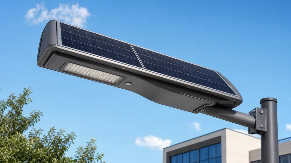
All-in-One Configuration
In an all-in-one smart solar lighting system, the solar panel, battery, LED module, and controller are integrated into a single housing unit. Installation is straightforward: mount the unit on the pole arm, connect the pole ground wire, and the system is operational. No separate panel wiring, no external battery box, no cable routing between components.
For distributors building a reseller SKU, the all-in-one format is easier to stock, easier to ship, and easier for end-user installation teams to handle — fewer components means fewer installation errors and fewer missing-parts complaints.
The trade-off is output ceiling and battery service access. All-in-one housings have a physical size limit that constrains the solar panel area and battery capacity. For most road and pathway projects up to 60W LED output with 3–4 autonomy nights, the all-in-one configuration is sufficient. Above that threshold — higher lumen output, longer autonomy, or difficult climates — the split configuration is the better choice.
Best suited for
- Standard distribution SKUs and reseller inventory
- Projects up to 60W LED output, 3–4 autonomy nights
- Markets where installation simplicity is a priority
- Lower-latitude deployments with adequate winter irradiance
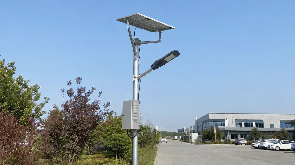
Split Configuration
In a split smart solar street lighting system, the solar panel is mounted separately from the LED fixture, typically on a dedicated panel bracket at the top of the pole or on an adjacent surface. The battery pack is housed in a separate enclosure, either at the base of the pole or in a mid-pole compartment.
This separation allows a larger panel area, a larger battery capacity, and — critically — battery service access without dismounting the fixture. For projects in high-latitude markets where winter irradiance is low, or for applications requiring 5–7 autonomy nights, the split configuration is the standard choice.
The split configuration also supports higher LED power — up to 200W in our standard range — because the panel and battery are not constrained by the fixture housing dimensions. For smart solar street lighting on main roads, highways, or large parking areas where lux requirements are high, the split system is the appropriate specification.
Best suited for
- High-output projects up to 200W LED, 5–7 autonomy nights
- High-latitude markets (above 50° latitude) with low winter irradiance
- Main roads, highways, and large parking areas with high lux requirements
- Applications where battery serviceability matters
A note on high-latitude specification
We've seen buyers specify all-in-one systems for Northern European projects to save on installation cost, then deal with runtime complaints from October through February. The freight saving on the all-in-one doesn't offset the warranty claim cost. For anything above 50° latitude, we recommend the split configuration as the default.
Which Configuration for Your Market
Choose All-in-One when:
- Building standard distribution SKUs or reseller inventory
- Smaller projects where installation simplicity is a priority
- Markets at lower latitudes with consistent year-round irradiance
- LED output requirements up to 60W with 3–4 autonomy nights
Choose Split when:
- High-output projects or high-latitude markets (above 50°)
- Long-autonomy requirements of 5–7 nights
- Main roads, highways, or large parking areas with high lux requirements
- Applications where battery serviceability matters
Both configurations are available with the same control options, sensor types, and IoT communication modules. The configuration choice affects physical form factor and sizing ceiling — not the intelligence or connectivity of the system.
Market Segments Where Smart Controls Protect Margin
Smart solar lighting commands a higher price point than standard solar lights. That margin is defensible when the system is configured correctly for the application and when the buyer is selling into segments where the smart features — dimming, motion sensing, remote monitoring — have measurable value. The segments below are where our buyers are building profitable programs.
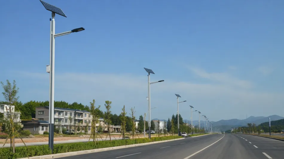
Municipal Road and Street Upgrades
Highest-volume segment
Municipal procurement for road lighting upgrades is one of the highest-volume segments for smart solar street lighting. Tenders typically specify lux levels, autonomy nights, control capability, and certification requirements. IoT solar lighting with remote monitoring is increasingly specified in municipal tenders because it reduces maintenance dispatch costs — the control system reports faults before a resident complaint triggers a work order.
Buyer Requirements for This Segment
- CE certification and IEC 62124 compliance
- Documentation packages that support bid submissions
- Specified lux levels, autonomy nights, and control capability
- Remote monitoring to reduce maintenance dispatch costs
Typical Order Volume
500 – 5,000 units per tender
Replacement Cycle
3 – 5 years
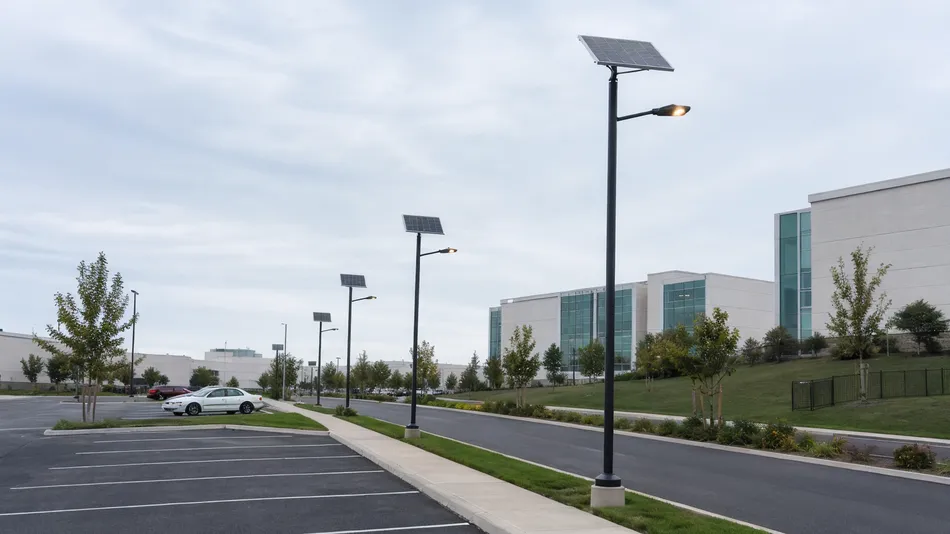
Parking Lots and Campus Lighting
Commercial & institutional
Commercial parking operators, universities, hospitals, and corporate campuses specify smart solar lighting for parking areas, internal roads, and perimeter routes. The value proposition is infrastructure cost reduction — no trenching, no grid connection fees, no ongoing electricity cost — combined with the operational benefit of motion-sensor dimming, which extends battery life in low-traffic periods.
Segment-Specific Requirements
- Warm color temperature: 3000K – 4000K
- Consistent pole design and aesthetic alignment
- Custom branding options — OEM/ODM configuration common
- Motion-sensor dimming to extend battery life in low-traffic periods
Campus sustainability programs have driven significant growth in this segment over the last three years. Worth building into your product line if you're targeting institutional buyers.
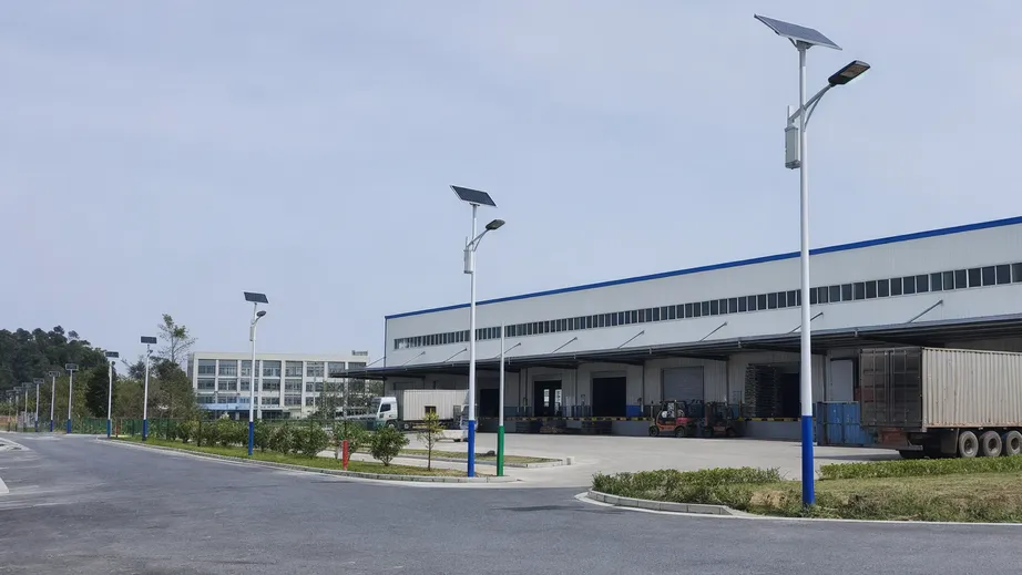
Logistics Yards and Industrial Parks
Industrial park operators and logistics facility managers source smart solar lighting for perimeter roads, loading areas, and internal circulation routes. The primary value is infrastructure cost reduction on large sites where grid extension would require significant civil works.
Motion-sensor dimming is particularly valuable in logistics yards where traffic is concentrated in shift-change windows and the site is largely empty between shifts. The system runs at 30–40% output during quiet periods and returns to full output on motion detection, extending battery life and reducing the panel and battery size required for the specification.
Why dimming matters for this segment
- 30–40% output during off-peak hours reduces energy draw significantly
- Full output restored instantly on motion detection at shift changes
- Smaller battery and panel specification lowers per-unit cost
- No grid extension civil works required on large sites
Project-based orders with follow-on purchases as the facility expands.
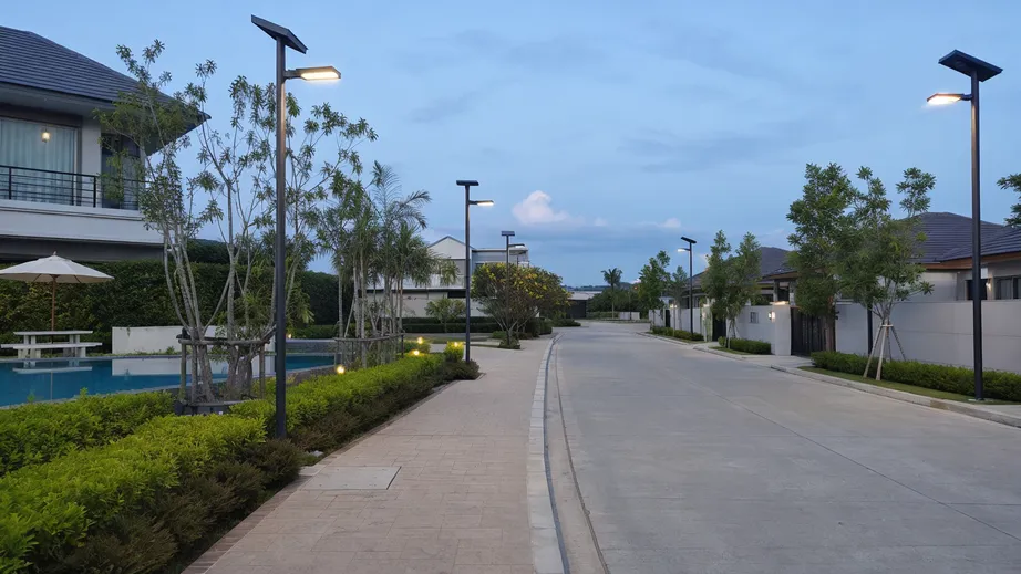
Residential Communities and Resort Infrastructure
Residential developers and resort operators source smart solar lighting for internal roads, pathways, and amenity areas. The buying pattern is typically project-based — a developer sources 200–500 units for a single development, then returns for the next project.
Warm color temperature (2700K–3000K), low-glare optics, and quiet pole design are the differentiating specs in this segment. The dimming capability and motion-sensor mode reduce energy consumption and extend battery life in low-traffic areas, which translates to a smaller battery and panel specification — and a lower unit cost — compared to a fixed-output system running the same hours.
Key specification priorities
- Warm CCT 2700K–3000K for residential and hospitality ambiance
- Low-glare optics suited to pedestrian pathways and amenity zones
- Quiet pole design that integrates with landscaped environments
- Dimming + motion-sensor mode reduces battery and panel size vs. fixed-output
Developer returns for follow-on orders with each new project phase.
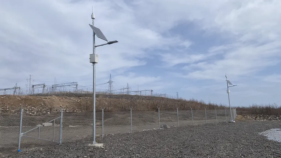
Remote Perimeter and Off-Grid Security Sites
Mining operations, agricultural facilities, border infrastructure, and utility substations need lighting without grid access. Smart solar lighting with 4G communication and 5–7 autonomy nights is the standard specification for these sites.
The IoT solar lighting capability allows remote fault monitoring without sending a technician to the site — a meaningful operational cost reduction for buyers supplying remote-site operators.
Battery Sizing Note
Battery sizing for these applications is conservative: we calculate for the worst-case irradiance month at the installation latitude, not the annual average.
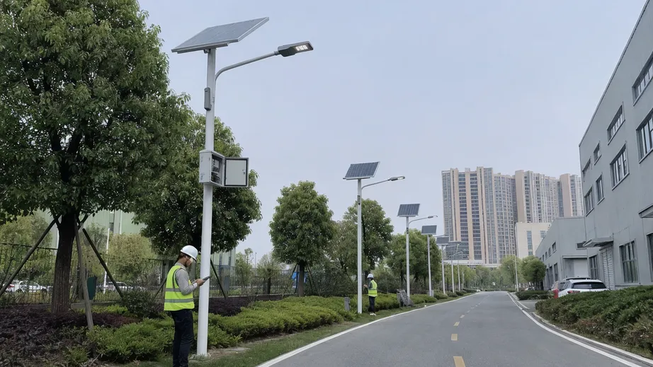
Smart-City Pilot Programs
Smart-city procurement programs typically start with a pilot installation — 50–200 units in a defined area — before scaling to a full deployment. IoT solar lighting with remote monitoring, dimming control, and data reporting capability is the standard specification for these pilots.
The communication module and monitoring dashboard configuration need to match the integrator's platform. Buyers supplying smart-city integrators need a manufacturer who can configure the communication protocol and firmware to the integrator's specification, not just ship a standard product.
Segment Sales Cycle Note
This segment has a long sales cycle but high repeat value — a successful pilot typically converts to a 2,000–10,000 unit deployment.
Dimming logic reduces hardware cost across both segments
Whether the site is a logistics yard with concentrated shift-change traffic or a residential pathway with low overnight pedestrian flow, the underlying cost benefit is the same: a system that dims during low-activity periods requires a smaller battery and panel to meet the same runtime specification. That reduction in hardware size flows directly into a lower unit cost — and a more competitive landed price for the buyer.
Explore Segment-Specific Solar Lighting Options
Parking lots, roadways, and area lighting — each with segment-matched specifications.
Control Logic, Sensors, and IoT Options Buyers Should Specify
The "smart" in a smart solar lighting system lives in the controller, sensor, and communication layer. These choices affect battery sizing, system cost, maintenance visibility, and what you can promise buyers in a project bid.
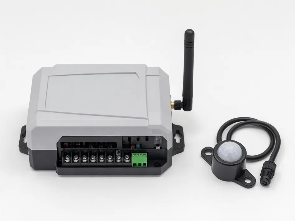
Why the control layer matters for cost
Time-based dimming alone reduces average power draw by 40–60% compared to full-output operation. That reduction directly lowers the battery capacity and panel wattage required for a given autonomy target — and therefore the system cost. Every control option you specify has a measurable effect on BOM.
Not every project needs IoT
A system with time-based dimming and a motion sensor, programmed to a fixed schedule, operates autonomously without any network connection. For projects in areas with limited cellular coverage, or buyers whose customers don't have a monitoring platform, standalone operation is the practical choice.
Control and Sensor Options
Time Control & Dimming Schedule
The baseline control mode. The controller is programmed with a schedule before shipment: full output for the first 2–3 hours after dusk, reduced output (typically 30–50%) through the middle of the night, and off or minimal output before dawn.
Best for
Standard distribution SKUs where cost-efficiency is the primary driver
PIR Motion Sensor
Adds motion-triggered override to the dimming schedule: the system dims to the programmed mid-night level, then returns to full output when motion is detected. Standard detection range is 8–12 meters at a 120° angle.
Best for
Roads, pathways, and open outdoor areas with unobstructed sensor view
Microwave Sensor
Detects motion through non-metallic materials and is not affected by rain or fog. The better choice for covered parking structures, bus shelters, or any application where the sensor doesn't have a clear line of sight.
Best for
Covered parking, bus shelters, and obstructed-sensor applications
PIR vs. Microwave: Decision Summary
| Criterion | PIR Sensor | Microwave Sensor |
|---|---|---|
| Detection range | 8–12 m, 120° cone | Adjustable; penetrates non-metallic materials |
| Rain / fog performance | False activations possible in heavy rain | Unaffected by rain or fog |
| Covered structures | Not suitable — obstructed line of sight | Suitable — detects through non-metallic covers |
| High-wind environments | Generally stable | More prone to false triggers from moving vegetation |
| Sensitivity calibration | Fixed hardware cone | Adjustable in controller firmware |
| Relative cost | Lower | Higher |
| Default recommendation | Most outdoor road and pathway applications | Only where PIR limitations are a real constraint |
IoT Communication Options
Standalone Non-Networked Operation
Not every smart solar lighting project needs IoT connectivity. A system with time-based dimming and a motion sensor, programmed to a fixed schedule, operates autonomously without any network connection. The controller firmware is locked to the programmed schedule at shipment.
4G IoT Communication
The most widely deployed option — coverage is available in most urban and peri-urban markets, and the data cost for lighting telemetry is low. A 4G module draws 2–5W continuously, which adds 20–50Wh to the daily battery draw on a 10-hour operating schedule. This draw is included in the battery sizing calculation for 4G-equipped systems.
NB-IoT
Preferred for dense urban deployments where network congestion is a concern and data volumes are low. NB-IoT operates on licensed spectrum with lower power consumption than 4G, making it well-suited for high-density municipal rollouts.
Zigbee and LoRa (Mesh Networks)
Used for mesh networks in campus or industrial park installations where a local gateway is available and cellular coverage is not required. The choice depends on your target market's network infrastructure and your buyer's monitoring platform.
Controller & Monitoring Architecture
Group Control, Remote Dashboard, and Multi-Site Management
For deeper controller and monitoring architecture — including group control, remote dashboard configuration, and multi-site management — see the Solar Lighting Control System page.
Control & IoT Option Quick Reference
| Option | Battery Impact | Network Required | Typical Application |
|---|---|---|---|
| Time-based dimming | Reduces draw 40–60% | None | All applications; baseline feature |
| PIR motion sensor | Minimal (passive sensor) | None | Roads, pathways, open outdoor areas |
| Microwave sensor | Slightly higher than PIR | None | Covered parking, bus shelters |
| Standalone (no IoT) | No additional draw | None | Low-coverage areas; no monitoring platform |
| 4G IoT | +20–50 Wh/day (2–5W module) | 4G cellular | Municipal, smart-city, remote monitoring |
| NB-IoT | Lower than 4G | NB-IoT licensed spectrum | Dense urban, high-density rollouts |
| Zigbee / LoRa | Low (mesh protocol) | Local gateway | Campus, industrial park, no cellular |
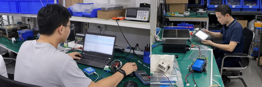
Battery, Controller, LED, and Waterproof Checks That Reduce Warranty Claims
Smart solar lighting fails at predictable points. We've been manufacturing this category long enough to know exactly where the failures originate, and the factory is built around preventing them. Here's what we check, and what it means for your warranty claim rate.
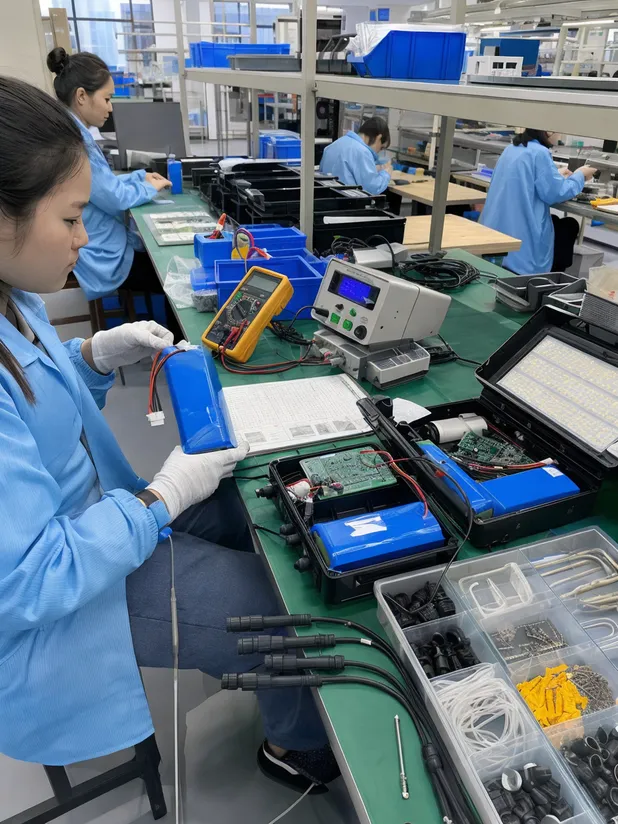
100% Outgoing Inspection
- Lighting modes & sensor response
- Controller function verified
- Battery charge state confirmed
- Accessory completeness checked
- Custom labeling vs. approved artwork
Controller Board Assembly on Automated SMT Lines
Charge/discharge logic · Dimming response · Sensor input · Communication handshake
The controller manages battery charge/discharge, LED dimming, sensor input, and communication output simultaneously. A controller assembled with inconsistent solder joints or misplaced surface-mount components will pass a bench test and fail in the field after thermal cycling. Our automated SMT lines place and solder controller and sensor circuit boards with machine precision — solder joint consistency is tight across the full batch, not just the first units off the line.
After SMT, every controller board goes through a function test: charge/discharge logic, dimming response, sensor input, and communication module handshake. Boards that fail function test don't reach final assembly. Manual SMT is where you start seeing variation in driver performance between units — we moved away from it on all controller boards years ago.
Battery Pack Capacity and Internal Resistance Testing
Most common warranty claim source — caught at the station, not in the field
Battery failure is the most common cause of smart solar lighting warranty claims. The failure mode is usually not a dead cell — it's a weak pack that passes a visual check but has elevated internal resistance, which means it can't deliver rated capacity under load after 50–80 charge cycles. We test every battery pack for capacity, internal resistance, and charge/discharge behavior before it's paired with a controller. Packs that fall outside tolerance are rejected at this station, not discovered in the field.
For LiFePO4 packs, we also verify cell matching within the pack: cells with more than 5% internal resistance variance are not assembled together, because mismatched cells accelerate degradation in the weakest cell and shorten the pack's effective life.
Aging test racks run finished units through multi-day charge/discharge cycles before final inspection. This catches early-life failures — units that would have failed within the first 30 days of deployment — before they leave the factory.
LED Module Lumen Output and CCT Confirmation
Batch consistency — front of container matches back of container
Lumen depreciation and color temperature drift across a batch are the two quality issues that generate the most buyer complaints in solar lighting. Both originate at the LED module assembly stage. We test every LED module for lumen output and color temperature before it goes into a housing.
Rejection Tolerances
IP65/IP67 Waterproof Structure Inspection
IP ratings are tested, not assumed
The most common waterproof failure in outdoor solar lighting is not the housing itself — it's the cable entry points and the junction between the housing and the lens or cover. We pressure-test every IP65/IP67 housing after final assembly: positive air pressure is applied to the sealed enclosure and checked for pressure drop over a hold period.
A housing that passes visual inspection but has a micro-gap at a cable gland will fail this test. For battery compartments specified at IP67, the compartment is tested separately from the main fixture.
Pressure Test Method
Positive air pressure applied to sealed enclosure → pressure drop monitored over hold period → micro-gaps at cable glands detected before shipment
100% Outgoing Inspection
Every unit is function-tested before the container loads: lighting modes, sensor response, controller function, battery charge state, and accessory completeness. Custom labeling and private-label packaging are checked against approved artwork at this stage. The result is that your packing list matches your container, and your container matches the spec you approved.
OEM/ODM Variables and Limits Before Sample Approval
Smart solar lighting is a system product — OEM/ODM customization goes deeper than changing a logo. The variables below are what we actually adjust for buyers building their own product lines or project-specific configurations, along with the limits that affect MOQ and lead time.
Performance Configuration
- Lumen output adjusted by LED configuration and driver current — hit a specific lux level for a project spec rather than shipping a standard output
- Color temperature 2700K–6500K; warm-white (2700K–3000K) for hospitality and residential, 5000K–6000K for road and industrial
- Battery capacity sized to required autonomy nights based on target latitude and seasonal irradiance data — we run the calculation, not just accept a number from a spec sheet
- Solar panel wattage matched to battery capacity and installation latitude's winter irradiance
Controller Firmware & Sensor Configuration
- Firmware programmed to your specified dimming schedule before shipment; can be locked to prevent field modification — useful for large installations requiring consistent system behavior
- PIR detection range and angle, microwave sensitivity threshold, and motion-trigger hold time all configurable
- For OEM buyers with a specific operating schedule requirement, firmware is programmed to spec during sample production and confirmed before mass production approval
Communication Protocol Selection
- 4G for most markets; NB-IoT for dense urban deployments; Zigbee or LoRa for campus mesh networks
- If your buyer has an existing monitoring platform, we configure the communication module to report to it rather than requiring a new dashboard
- Unsupported communication protocols or custom API integrations require engineering review before feasibility can be confirmed — this is not a standard catalog option and affects lead time
Housing, Branding & Packaging
- Housing color in standard options (black, dark grey, silver) and custom RAL colors on OEM orders
- Logo placement on fixture, pole bracket, and packaging standard for OEM programs
- Carton labeling, user manuals, and compliance documentation produced under your brand
- CE declarations, RoHS certificates, IP test reports, and IEC 62124 test data prepared under your product specifications for markets with specific import documentation requirements
MOQ and Configuration Limits
Standard catalog models — low enough to test a new SKU before committing to a full program.
OEM/ODM orders with custom specifications — modified lumen output, custom firmware, private-label packaging, non-standard housing color — depending on scope of component or tooling changes.
Runtime Cannot Be Guaranteed Without Site Data
If you specify a battery capacity without providing installation latitude and operating schedule, we'll flag it before production rather than ship a system that underperforms in the field. Engineering review is included in the OEM process; we don't charge separately for configuration work on orders that proceed to production.
Packing, Kitting, Documentation, and Batch Traceability
A smart solar lighting system ships as a multi-component package: fixture or all-in-one housing, solar panel, battery pack, controller (if separate), mounting hardware, sensor module, and — for IoT-equipped systems — the communication module and antenna. Each component needs its own protective packing, and the full system needs to arrive with the documentation your import process requires.
Export Packing for System Components
Fixtures & All-in-One Housings
Packed in double-wall export cartons with foam corner protection and internal dividers.
Solar Panels
Individually wrapped and packed flat with foam interleaving.
Battery Packs
Packed separately from electronics in compliance with lithium battery shipping regulations. UN38.3 test reports available for air freight and for sea freight markets that require them.
Mounting Hardware & Accessory Packs
Bagged and labeled by component type, reducing on-site assembly errors. For split-system orders, the panel bracket, battery enclosure, and fixture are packed in separate cartons with assembly hardware in a labeled accessory bag.
Compliance Documentation Per Shipment
Standard Documentation — Every Shipment
CE Declaration of Conformity
Included with every shipment
RoHS Compliance Certificate
Included with every shipment
IP65/IP67 Test Reports
Included with every shipment
ISO 9001:2015 QMS Certification
Included with every shipment
IEC 62124 Test Data
Available on request for buyers whose procurement process requires solar performance verification. For OEM buyers, compliance documentation is prepared under your product specifications and brand.
Batch Traceability
Every carton carries a batch code
Links to the production run, incoming material records, and QC inspection data. If a warranty issue surfaces in the field, you can isolate the affected production batch without pulling your entire inventory.
For OEM buyers with private-label programs, batch codes are integrated into your labeling format.
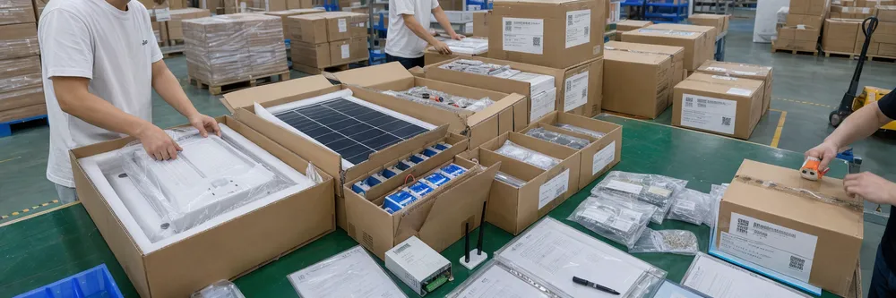
Multi-Component Kitting
Fixture, panel, battery, controller, hardware, sensor, and IoT module — each component packed and labeled separately to reduce on-site assembly errors
Import-Ready Documentation
CE, RoHS, IP test reports, ISO 9001:2015, and IEC 62124 data available — OEM buyers receive documentation under their own product specifications and brand
Batch-Level Warranty Isolation
Batch codes link to production run, incoming material records, and QC data — isolate a warranty issue to a specific batch without pulling your full inventory
Choose the Right Smart Solar Lighting Product Path
This page covers the complete configurable smart solar lighting system — the right starting point for most road, pathway, parking, and campus lighting projects where the primary requirement is a reliable autonomous system with adjustable brightness modes. If your project or product line has a more specific requirement, the sibling products below may be the better fit.
Sibling Product
Smart Solar Poles
If your project specifies a pole-integrated design — where the solar panel, battery compartment, LED fixture, and controller are built into a single pole structure — the smart solar poles page covers that product. Smart solar poles are specified for urban streetscape projects, campus infrastructure, and smart-city demonstration installations where the visual integration of the system matters alongside the lighting performance. The pole is the product, not a mounting accessory.
View Smart Solar PolesSibling Product
Solar Lighting Control System
If your requirement is the controller and communication layer — group control units, remote monitoring systems, or IoT solar lighting management for a large installation — the solar lighting control system page covers the controller and monitoring architecture in depth. Relevant for project contractors who need centralized control over a large deployment, and for OEM buyers who want to integrate a specific control architecture into their own product line.
View Solar Lighting Control SystemSibling Product
Solar Street Light With Camera
If your project is security-driven — perimeter lighting with integrated surveillance, parking monitoring, remote site security — the solar street light with camera page covers the combined lighting and camera system. The camera module draws from the same battery system as the LED fixture, and the power budget is sized to support both loads. IP67-rated camera module, 4G communication, and 5–7 autonomy nights are the standard specification for this product.
View Solar Street Light With CameraProcurement FAQ for Smart Solar Lighting System Buyers
Sizing, autonomy, and specification questions that come up before purchase orders are placed. Answers are based on real project parameters — not generic guidance.
How do you size the battery and solar panel for a smart solar lighting system?
Battery capacity is calculated from three variables: LED power draw (plus any communication module draw), operating hours per night, and required autonomy nights.
Worked Example
LED Power Draw
40W
Operating Hours
10 hrs/night
Autonomy Nights
3 nights
LiFePO4 chemistry is rated at 80% depth of discharge — installed capacity must be sized above the usable minimum accordingly.
Solar panel wattage is then sized to recharge that battery in the available peak sun hours at the installation latitude, calculated at winter solstice irradiance — not the annual average.
Send us your installation country, LED power requirement, operating hours, and autonomy target — we'll run the sizing and come back with a specific battery and panel specification.
How many autonomy nights should a project specify?
The autonomy specification directly drives battery capacity and system cost. Over-specifying adds cost without adding reliability in high-irradiance markets; under-specifying generates warranty claims in low-irradiance markets.
North America & Europe
3–5 nights
Middle East, Southeast Asia & Sub-Saharan Africa
2–3 nights — higher irradiance means faster battery recovery.
High-Latitude Markets (above 55°) or Consistently Overcast Climates
5–7 nights
If you're unsure, tell us the installation country and we'll recommend the appropriate autonomy target based on the seasonal irradiance data for that location.
Is all-in-one or split better for smart solar street lighting?
Is all-in-one or split better for smart solar street lighting?
For standard distribution SKUs, smaller projects, and markets where installation simplicity is a priority: all-in-one. For LED power above 60W, autonomy requirements above 4 nights, high-latitude markets, or applications where battery serviceability matters: split.
- Standard distribution SKUs
- Smaller projects
- Markets where installation simplicity is a priority
- Southeast Asia and Middle East standard road projects
Easier to stock and install; panel and battery constrained by fixture housing dimensions.
- LED power above 60W
- Autonomy requirements above 4 nights
- High-latitude markets
- Applications where battery serviceability matters
Supports higher output and longer autonomy; panel and battery not constrained by fixture housing. Default choice for Northern Europe and Canada buyers.
Regional default: Most buyers in Northern Europe and Canada default to split; most buyers in Southeast Asia and the Middle East default to all-in-one for standard road projects.
PIR or microwave sensor: which is better for smart solar lighting?
PIR or microwave sensor: which is better for smart solar lighting?
PIR is the right choice for most road and pathway applications — it's lower cost, lower power draw, and sufficient for any application with a clear line of sight to approaching traffic or pedestrians. Microwave is the better choice for covered parking structures, bus shelters, or consistently wet climates where rain would trigger PIR false activations.
| Criterion | PIR Sensor | Microwave Sensor |
|---|---|---|
| Power draw | Less than 0.5W | 1–2W |
| Cost | Lower | Higher |
| Detection method | Infrared (line of sight) | Microwave (penetrates barriers) |
| False trigger in rain | Significant risk | Not affected |
| Best environment | Open roads, pathways, clear sightlines | Covered parking, bus shelters, wet climates |
| Recommended for | Standard outdoor road or pathway | Covered or consistently wet environment |
Your project is a standard outdoor road or pathway application with clear line of sight to approaching traffic or pedestrians.
Your project involves covered parking structures, bus shelters, or consistently wet climates where rain would trigger PIR false activations.
The practical difference in battery draw is small — PIR draws less than 0.5W, microwave draws 1–2W — but the false-trigger rate difference in the wrong environment is significant.
Does IoT solar lighting require cellular coverage at the installation site?
Does IoT solar lighting require cellular coverage at the installation site?
4G IoT solar lighting requires cellular coverage — if the installation site has no 4G signal, the communication module can't connect. For sites with limited cellular coverage, NB-IoT is an option in markets where NB-IoT networks are deployed, as it operates on a narrower frequency band with better penetration.
For campus or industrial park installations with a local gateway, Zigbee or LoRa mesh networks operate independently of cellular coverage. For sites with no network infrastructure at all, standalone operation with a programmed dimming schedule is the practical choice — the system operates autonomously without any communication module.
Match communication spec to actual site infrastructure
4G / NB-IoT
Requires cellular coverage; NB-IoT offers better penetration in weak-signal areas where deployed
Zigbee / LoRa mesh
Campus or industrial park use with local gateway; independent of cellular coverage
Standalone operation
Programmed dimming schedule; no communication module required; fully autonomous
Specify the communication requirement based on the site's actual network infrastructure, not the ideal scenario.
What certifications and documents are available for export orders?
What certifications and documents are available for export orders?
Standard documentation with every shipment: CE declaration of conformity (covering LVD and EMC directives), RoHS compliance certificate, IP65/IP67 test reports, and ISO 9001:2015 quality management certification. IEC 62124 test data is available on request — increasingly required in European municipal tenders for solar performance verification.
For lithium battery packs, UN38.3 test reports are available for air freight and sea freight markets that require them.
Standard with every shipment
- CE declaration of conformity (LVD and EMC directives)
- RoHS compliance certificate
- IP65/IP67 test reports
- ISO 9001:2015 quality management certification
Available on request
- IEC 62124 test data (European municipal tenders)
- UN38.3 test reports for lithium battery packs (air/sea freight)
- SASO (Saudi Arabia) — confirm at inquiry stage
- SAA/RCM (Australia) — confirm at inquiry stage
OEM buyers
Compliance documentation is prepared under your product specifications and brand. CE declarations, RoHS certificates, IP test reports, and IEC 62124 data can all be issued under your product name.
For market-specific requirements beyond CE, confirm the requirement at the inquiry stage and we'll advise on availability. See JXSOL certifications and compliance documentation for the full list of current documentation.