

Smart Solar Poles Built as Complete Project Infrastructure
Pole body, LED fixture, solar panel, battery compartment, controller, and optional IoT module in one engineered unit.
JXSOL has manufactured solar-powered outdoor lighting since 2012. Our smart solar poles are specified for municipal streetscape, campus, industrial park, and smart-city projects where the pole is the product — not a mounting accessory for a separate solar light.
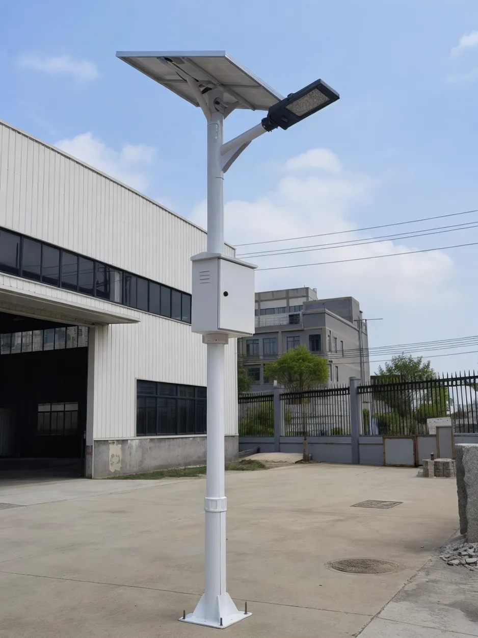
Smart Solar Poles Built as Complete Project Infrastructure
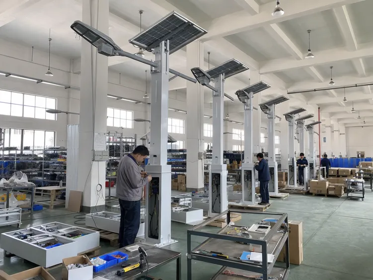
A smart solar pole is not a standard solar street light with a pole attached. The pole body, solar panel mounting structure, battery enclosure, LED fixture, controller, wiring harness, and optional IoT or camera hardware are engineered as a single unit — designed together, tested together, and shipped as a complete system. When you source a smart solar pole from JXSOL, you're sourcing a project-ready infrastructure product, not a collection of components that need to be integrated on-site.
We've been manufacturing solar-powered outdoor lighting since 2012. Smart solar poles sit at the engineering-intensive end of our product range — the pole has to handle wind load with a solar panel mounted at height, the battery compartment needs its own IP-rated enclosure separate from the fixture, and the wiring between the panel, battery, controller, and LED module has to be routed cleanly through the pole body without creating maintenance problems later. All of that is resolved in the design, not left to the installer.
For buyers sourcing for resale, project supply, or OEM/ODM programs, the integrated design means one supplier, one QC process, one warranty, and one point of contact when something needs to be resolved.
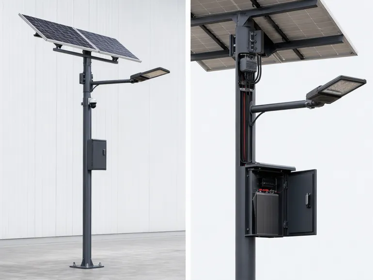
Integrated System Components
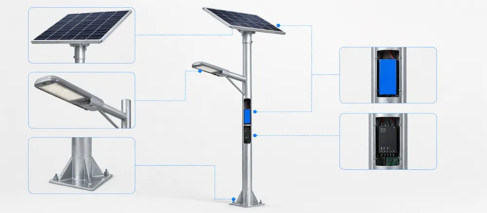
- Pole body — engineered for wind load with panel at height
- Solar panel mounting structure — integrated, not field-fitted
- IP-rated battery enclosure — separate from the fixture
- LED fixture — matched to system wattage and lumen output
- Controller & wiring harness — routed through pole body, factory-terminated
- Optional IoT / camera module — pre-wired mounting provision
Where Pole Integration Protects Your Project Margin
The alternative to a smart solar pole is sourcing the pole, fixture, solar panel bracket, battery box, controller enclosure, and wiring separately — from two or three suppliers — and coordinating the integration on-site. That approach has a cost that doesn't show up in the unit price.
Split-Sourcing Hidden Costs
- Installation labor for field integration of separate components
- Component compatibility risk across multiple supplier specs
- Split warranty accountability — suppliers point at each other on failures
- Downstream exposure when one component fails post-installation
- Battery capacity errors discovered after first winter, not at configuration
- Cable entry seal failures surfacing as warranty claims six months post-install
JXSOL Integrated Pole Advantages
- System configured and tested as a unit before leaving the factory
- Battery capacity verified against installation latitude at configuration stage
- IP pressure test catches cable entry seal issues before shipment
- One supplier, one QC process, one warranty, one point of contact
- Pole arrives pre-assembled and pre-wired — set foundation, erect, connect ground cable, operational
- No field wiring, no separate panel bracket alignment, no independent controller box sealing
The Margin Math Is Straightforward
When a field integration problem surfaces post-installation — a battery that underperforms in winter, a cable entry that lets moisture in, a bracket that wasn't rated for the panel weight — the cost lands on you, not the component supplier. An integrated pole shifts that risk upstream, where it belongs.
Distributors and EPC contractors who have switched to integrated pole procurement consistently report fewer post-installation service calls and cleaner warranty resolution. The unit price difference is recovered in the first callback avoided.
Pole Configuration Parameters
Every smart solar pole is configured at the order stage, not assembled from generic stock. The parameters below define what gets specified — and why each one matters to system performance.
Pole Height
Typically 4 m to 12 m depending on application. Height determines wind load class, foundation spec, and panel elevation angle options.
Solar Panel Wattage
Sized against fixture wattage, daily burn hours, and installation latitude. Undersizing here is the most common cause of winter autonomy failure.
Battery Capacity
Specified in Ah at system voltage. Autonomy days (consecutive cloudy days the system sustains full output) is the design target, not raw Ah.
LED Fixture Wattage & CCT
Wattage sets the energy budget; CCT (colour temperature) is a project or regulatory requirement. Both are locked at configuration, not field-adjusted.
Controller Mode
Dusk-to-dawn, motion-adaptive, or time-segmented dimming profiles. Controller mode directly affects battery autonomy — adaptive modes extend run time significantly.
Wind Load Zone
Pole wall thickness and base flange are engineered to the project's wind zone. A panel at 8 m adds significant sail area — this is not a generic structural spec.
Configuration Is Done at Order Stage
JXSOL's technical team reviews each project's latitude, fixture wattage, burn hours, and wind zone before confirming the configuration. This is not a catalogue selection — it's an engineered specification. Distributors and project buyers receive a configuration sheet with the order confirmation that documents every parameter and the design rationale behind it.
Where Smart Solar Poles Fit
The right application is one where grid connection is absent, expensive, or slow to permit. These are the contexts where integrated solar poles consistently outperform the alternatives.
Parking & Logistics Yards
Large paved areas with no existing grid infrastructure. Trenching cost per pole often exceeds the pole cost itself. Solar eliminates the trench entirely.
- No trenching across sealed surfaces
- Expandable — add poles without grid upgrade
- Optional CCTV / LPR camera integration
Roads & Highway Sections
Rural or peri-urban road sections where grid extension is uneconomical. Poles are spaced to lux level requirements without dependency on utility connection points.
- No utility connection point dependency
- Higher poles (8–12 m) with wider beam optics
- Wind-zone engineered for exposed locations
Campuses & Institutions
Universities, hospitals, and government campuses where grid connection permits are slow and disruptive. Solar poles deploy without electrical contractor coordination.
- No electrical permit required for installation
- Minimal disruption to existing landscaping
- Supports sustainability reporting metrics
Residential Developments
New subdivisions and gated communities where street lighting infrastructure is being installed from scratch. Solar eliminates the grid connection timeline dependency.
- Lighting operational before grid connection
- Lower ongoing electricity cost for HOA / developer
- Aesthetic pole finish options available
Industrial & Mining Sites
Remote sites where grid power is unavailable or unreliable. High-wattage configurations with extended battery autonomy for perimeter and access road lighting.
- Operates independently of site generator
- Heavy-duty pole spec for harsh environments
- Camera and sensor integration for site security
Parks & Public Spaces
Pathways, plazas, and recreational areas where underground cabling would damage root systems or heritage surfaces. Solar poles install with minimal ground disturbance.
- No underground cable — no root zone disruption
- Lower pole heights (4–6 m) for pedestrian scale
- Warm CCT options for amenity lighting character
Product Specification Planning for Smart Solar Pole Lighting
The table below covers typical specification ranges for JXSOL smart solar poles. Final specifications depend on installation latitude, required autonomy nights, pole height, LED power, and optional IoT or camera configuration. Contact us with your project parameters for a site-specific datasheet.
| Parameter | Typical Specification |
|---|---|
| Pole Height | 4m – 12m (standard); custom heights available |
| Pole Material | Hot-dip galvanized steel (standard); aluminum alloy (available) |
| Pole Cross-Section | Tapered round or octagonal; custom profiles on request |
| Surface Finish | Powder coat, 60–80μm; standard RAL colors; custom colors available |
| LED Power | 30W – 150W (matched to pole height and road width) |
| Lumen Output | 3,500 lm – 18,000 lm (typical; project-specific) |
| Color Temperature | 3000K, 4000K, 5000K, 6000K (standard); 2700K–6500K available |
| CRI | ≥70 (standard); ≥80 available |
| Solar Panel Wattage | 60W – 300W (sized to battery and installation latitude) |
| Battery Chemistry | LiFePO4 (standard); Li-ion (available) |
| Battery Capacity | 50Ah – 200Ah (project-specific autonomy sizing) |
| Autonomy Nights | 3–5 nights (standard sizing); up to 7 nights available |
| Battery Compartment | IP65-rated lockable access panel in pole body |
| Controller Modes | Time control, PIR motion sensor, microwave sensor, dimming schedule, remote/IoT |
| Communication Options | 4G, NB-IoT, Zigbee, LoRa (project-specific) |
| Sensor Options | PIR (120°, 8–12m range), microwave (adjustable sensitivity) |
| Camera Option | 2MP–4MP integrated, IP67-rated, night vision available |
| Ingress Protection | IP65 (fixture and panel junction); IP67 (battery compartment, camera module) |
| Operating Temperature | -20°C to +60°C |
| Wind Load Design | Typically rated to 35–45 m/s; site-specific structural calculation available |
| Warranty Support | 3 years |
| MOQ | 100 units (standard models); 500 units (OEM/ODM with structural changes) |
| Certifications |
ISO 9001:2015
CE
RoHS
IP65/IP67
IEC 62124
|
Specifications shown are typical values for this product type. Final specifications depend on site latitude, autonomy requirement, pole height, and load configuration. Request a project-specific smart solar pole datasheet.
Structural and Service Design Buyers Should Confirm Before Ordering
Smart solar poles involve structural decisions that affect both the installed cost and the long-term service cost of the project. These are the parameters worth confirming before the order is placed — not after the poles are on-site.
Wind Load and Panel Mounting Height
The solar panel is the largest wind-load surface on the pole. At 8–10 meters height, a 200W panel presents a significant lateral force in high-wind conditions. Our pole designs are calculated for wind loads at the panel mounting height, not just the pole base — the wall thickness, weld specifications, and anchor bolt pattern are all derived from the panel size and mounting position.
For projects in coastal areas, typhoon zones, or open industrial sites, we can provide a site-specific structural calculation.
We've seen poles from other suppliers fail at the panel bracket weld, not the pole body — because the bracket was designed for a smaller panel and then uprated without recalculating the joint.
Solar Panel Orientation and Seasonal Performance
The panel mounting angle is fixed at the factory. For most projects between 15° and 45° latitude, a fixed tilt angle equal to the installation latitude gives the best annual energy yield. For projects closer to the equator, a shallower tilt is more appropriate.
We set the panel angle based on your installation latitude — if you don't specify, we'll ask before production.
Getting this wrong by 10–15° can reduce annual energy yield by 8–12%, which compounds into shorter autonomy nights during winter months.
Battery Compartment Access and Maintenance Clearance
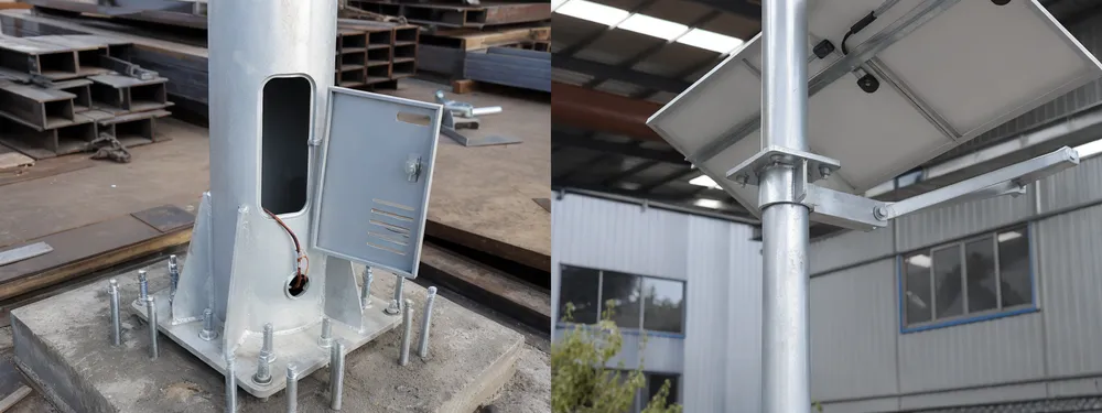
The battery compartment is built into the pole body, typically at 0.8–1.2 meters above ground level, with a lockable IP65-rated access panel. This placement keeps the battery accessible for maintenance without requiring a ladder, while keeping it above typical flood levels.
The compartment is sized for the battery pack, controller, and wiring connections — with enough clearance for a technician to disconnect and replace the battery pack without removing the pole.
For projects in public spaces, the lock specification matters: we use a standard utility key lock as default, but custom lock cylinders are available for projects that need a site-specific key.
Controller and Wiring Access
The controller is mounted inside the battery compartment on a DIN rail bracket, accessible through the same access panel as the battery. All wiring connections use weatherproof connectors with locking collars — no bare terminal blocks exposed to the compartment environment.
Cable entries at the pole base use compression glands with IP65 sealing. For IoT-enabled poles, the communication module antenna is routed to the exterior of the pole through a sealed port — the antenna needs line-of-sight clearance, and the port position is confirmed during the design review.
Foundation Coordination
Civil interface — confirm before production
Smart solar poles use a cast-in-place anchor bolt cage or a pre-cast foundation block, depending on the site conditions. We supply the anchor bolt cage drawing and foundation specification with the order — your civil contractor pours the foundation to our drawing, and the pole base plate bolts directly to the anchor cage.
For projects where the foundation design needs to match an existing streetscape standard, we can adjust the anchor bolt pattern and base plate dimensions.
This is a detail that's easy to coordinate before production and expensive to fix after the poles arrive on-site.
Project Segments Where Smart Solar Poles Sell as Infrastructure
Smart solar poles are specified where the pole itself is part of the project's visual and functional design — not just a mounting structure for a light. The segments below are where our buyers are building profitable programs.
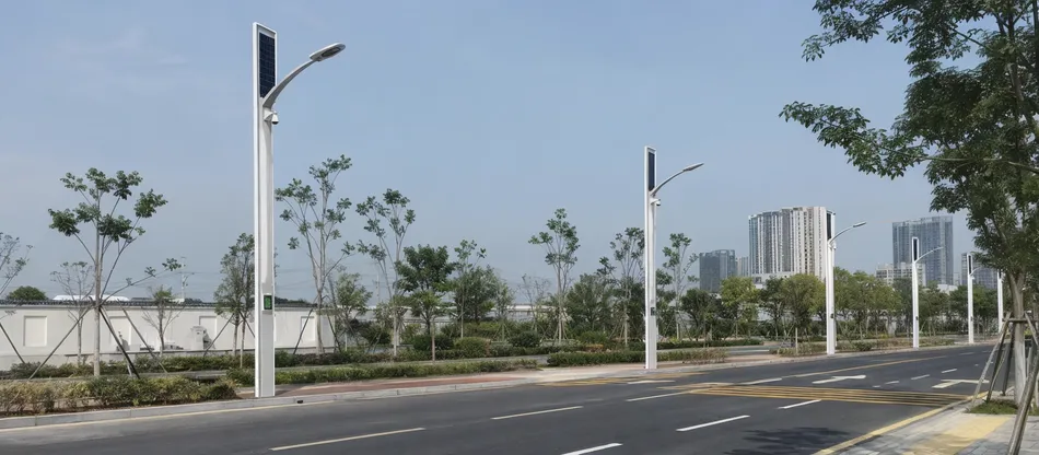
Municipal Streetscape and Road Upgrades
Municipal road lighting tenders increasingly specify integrated smart solar poles rather than standard solar street lights on separate poles. The visual consistency of a purpose-designed pole — with the panel integrated into the pole profile rather than mounted on a bracket — meets the aesthetic requirements of urban streetscape projects.
IoT-enabled poles with remote monitoring capability are specified in tenders because they reduce maintenance dispatch costs: the system reports faults before a resident complaint triggers a work order.
Procurement Requirements
- CE certification and IEC 62124 compliance required for bid submissions
- Full documentation packages to support tender submissions
- Remote monitoring capability for fault reporting before complaint-driven dispatch
Typical Order Volume
200–2,000 units per project, with repeat orders as the municipality extends the program to additional roads
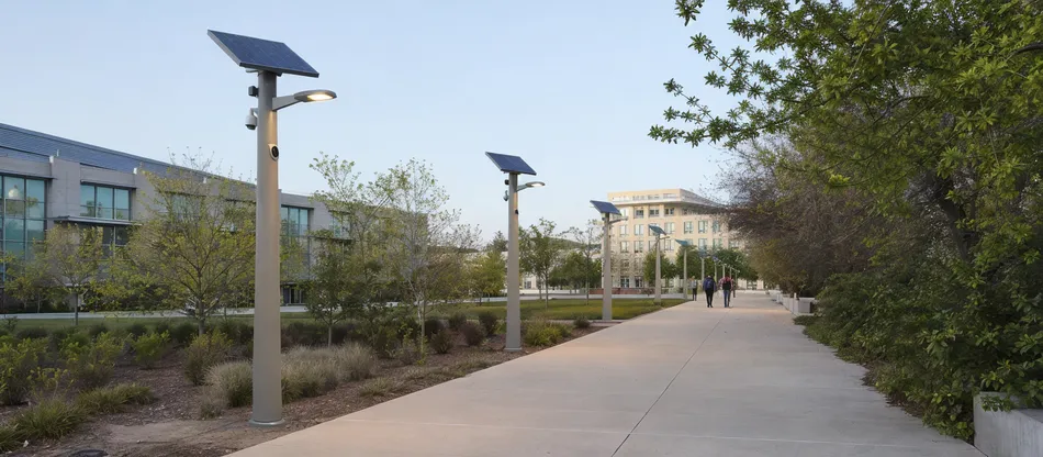
University, Hospital, and Corporate Campuses
Campus projects specify smart solar poles for pathways, parking areas, and perimeter roads. These projects combine performance requirements — lux levels, autonomy nights, sensor logic — with aesthetic requirements: warm color temperature (3000K–4000K), consistent pole design across the campus, and sometimes custom powder coat colors to match the institution's brand standards.
OEM/ODM configuration is common here. The procurement pattern is project-based but repeatable: a university that installs smart solar poles for one campus phase typically returns for the next phase with the same specification.
Specification Requirements
Segment Growth Note
This segment has grown significantly over the last three years — campus sustainability programs are driving procurement decisions that previously went to grid-tied LED.
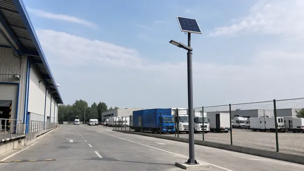
Industrial Parks & Logistics Yards
Industrial park operators and logistics facility managers source smart solar poles for perimeter roads, loading areas, and internal circulation routes. The value proposition is infrastructure cost reduction: no trenching, no grid connection fees, no ongoing electricity cost.
The integrated pole design reduces installation time on large sites where running conduit between separate components would add significant labor cost. For logistics yards with high vehicle traffic, the pole's structural specification — wall thickness, base plate size, anchor bolt pattern — matters more than the aesthetic design.
Structural configuration note: We can configure the structural spec for high-impact environments without changing the lighting or electrical configuration.
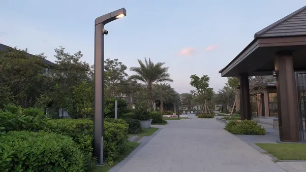
Resorts, Residential Communities & Public Parks
Residential developers and resort operators specify smart solar poles for internal roads, pathways, and amenity areas. The integrated pole appearance — no visible battery box, no external wiring, no bracket-mounted panel — is a selling point for premium developments where the infrastructure is part of the visual design.
Warm color temperature (2700K–3000K) and low-glare optics are the standard specification in this segment. Order volumes run 100–500 units per project, with the developer returning for the next project if the product performs.
Security option: Solar street light with camera is available for resort perimeter security where surveillance is also required.
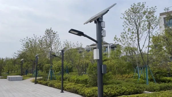
Smart-City Pilot Projects
Smart-city procurement programs typically start with a pilot installation of 50–200 units in a defined area before scaling to a full deployment. IoT-enabled smart solar poles with remote monitoring, dimming control, and data reporting capability are the standard specification for these pilots.
The pole's IoT readiness — communication module, antenna routing, remote firmware update capability — needs to be confirmed before the pilot, because the city's technical team will be evaluating the monitoring platform alongside the lighting performance.
Integrator support: We can configure the communication protocol to match the integrator's platform and provide the technical documentation the city requires for the pilot report.
Ready to specify for your project segment?
Tell us the site type, unit count, and structural requirements — we'll configure the right spec.
OEM/ODM Configuration Without Turning the Pole Into a Risky One-Off
Smart solar poles have more configurable variables than most solar lighting products — and more variables that require engineering review before production. Here's what we can adjust, what requires a design review, and what affects MOQ.
Standard Configurable Items
Available from 100 units
- Pole height (4m–12m)
- Powder coat color (any RAL)
- LED power (30W–150W), color temperature (2700K–6500K)
- Dimming schedule and sensor logic
- Battery capacity (within standard compartment size)
- Solar panel wattage (within standard mounting frame)
- Communication protocol (4G, NB-IoT, Zigbee, LoRa)
- Branding (logo on pole body, fixture, and packaging)
These variables are adjusted during the configuration review without changing the pole's structural design or tooling.
Items Requiring Engineering Review
Typically 500+ units
- Pole cross-section changes (round to octagonal, or custom profile)
- Battery compartment size changes (larger packs that don't fit the standard compartment)
- Non-standard panel mounting angles or dual-panel configurations
- Camera bracket integration at non-standard positions
- Anchor bolt pattern changes for non-standard foundation designs
Timeline note: Engineering review adds 5–7 working days to the sample timeline but prevents production problems that are far more expensive to resolve after tooling is committed.
Private-Label & Documentation Support
Standard for OEM programs
- Logo placement on pole body, fixture housing, and carton
- User manuals, installation guides, and compliance documentation under your brand
- CE declarations, RoHS certificates, IP test reports to your product specifications
- Full documentation package for markets with specific import documentation requirements
- Firmware lockable to prevent field modification — consistent system behavior across large installations
Honest Limitation on Custom Cross-Sections
Custom pole cross-sections require new tooling, which adds cost and lead time. For most OEM programs, the standard round or octagonal profile with a custom powder coat color and branding achieves the visual differentiation buyers need without the tooling investment. We'll tell you when a structural change is worth the cost and when it isn't.
Factory QC for Pole-Integrated Electronics, Battery, and Waterproof Points
A smart solar pole has more failure points than a standard solar street light — the battery compartment seal, the cable entries at the pole base, the panel junction box, the controller board, and the LED driver are all potential ingress or failure points. Our QC process is built around these specific risks.
Controller & Circuit Board Assembly
Controller and sensor circuit boards are assembled on automated SMT lines — solder joint consistency is tight across the full batch, not just the first units off the line. After SMT, every board goes through a function test: charge/discharge logic, dimming response, sensor input, and communication module handshake.
Boards that fail don't reach final assembly.
Why automated SMT matters: Manual SMT is where you start seeing variation in driver performance between units. We moved away from it on all controller boards years ago.
Battery Pack Testing & Cell Matching
Battery packs are tested for capacity, internal resistance, and charge/discharge behavior before pairing with a controller. For LiFePO4 packs, we verify cell matching within the pack: cells with more than 5% internal resistance variance are not assembled together.
Why cell matching matters: Mismatched cells accelerate degradation in the weakest cell and shorten the pack's effective life.
Finished units go through aging test racks — multi-day charge/discharge cycles — before final inspection. This catches early-life failures before they leave the factory.
Waterproof Verification — Every Unit
Waterproof verification is done with positive air pressure testing on every IP65/IP67 housing after final assembly — not a sample, every unit. The test applies pressure to the sealed enclosure and checks for pressure drop over a hold period.
Cable entries at the pole base, the battery compartment access panel seal, and the panel junction box are all tested as part of the complete pole assembly.
What this catches: A housing that passes visual inspection but has a micro-gap at a cable gland will fail this test.
LED Module & Lumen Consistency
LED modules are tested for lumen output and color temperature before installation. Modules outside ±10% of specified lumen output or ±200K of specified CCT are rejected.
What this means for your project: The poles at the end of the container perform the same as the poles at the front. Batch consistency is controlled at the module level, not just at final inspection.
100% Outgoing Inspection Coverage
Lighting modes and sensor response
Controller function and battery charge state
Accessory completeness and label accuracy
IoT communication module handshake (for IoT-enabled poles)
Custom labeling and packaging checked against approved artwork (OEM orders)
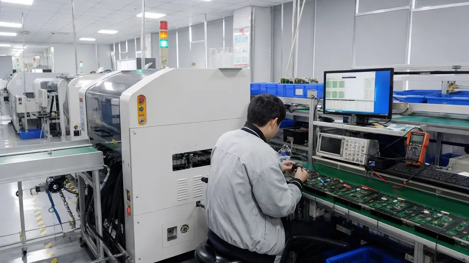
Automated SMT assembly and post-assembly function testing on every controller board before final integration.
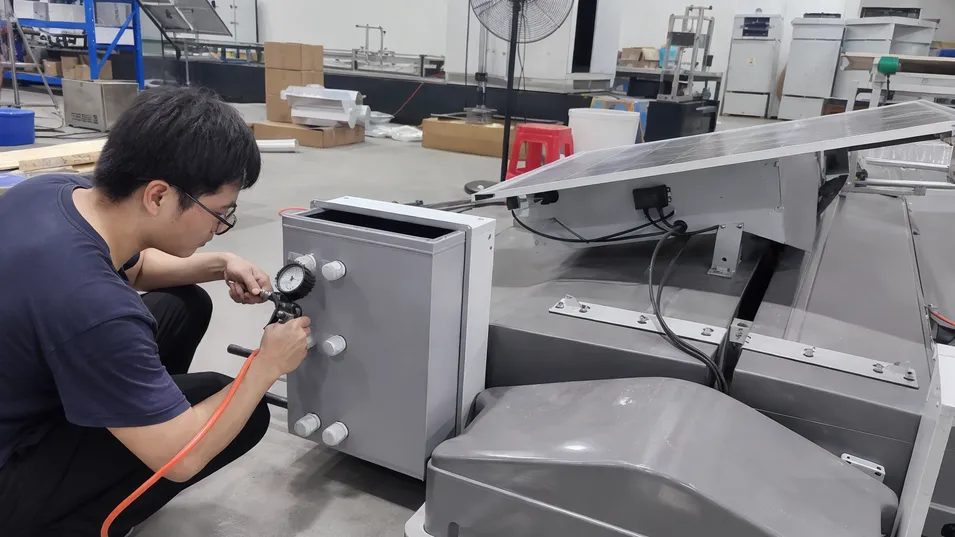
Positive air pressure waterproof testing on every completed pole assembly — battery compartment, cable entries, and panel junction box.
Certifications & Documentation
Provided with every shipment
ISO 9001:2015
Quality Management
CE
European Conformity
RoHS
Hazardous Substances
IP65/IP67
Ingress Protection
IEC 62124
Solar PV Systems
CE declarations, RoHS certificates, and IP test reports are provided with every shipment. Documentation can be produced under your brand for OEM programs.
Packing, Container Planning, and Site Delivery Control
Smart solar poles ship as multi-component packages. Getting the packing right protects your margin — a damaged pole section or a missing hardware bag generates a warranty claim and a delayed installation, not just a replacement part.
Component-Level Packing Design
- —Pole sections packed in reinforced export cartons with foam end caps and internal bracing — designed for the specific pole diameter and wall thickness, the most damage-prone component during container handling.
- —Solar panels individually wrapped and packed flat with foam interleaving.
- —Battery packs packed separately from electronics in compliance with lithium battery shipping regulations; UN38.3 test reports available for air freight documentation.
- —Controller and accessory hardware packed in a labeled accessory bag inside the battery compartment carton — the installer opens one carton and finds everything needed for that pole.
Container Loading and Site Delivery
Carton dimensions are planned to maximize 40HQ utilization. A typical 40HQ container holds 80–120 complete smart solar pole sets depending on pole height and panel size.
- —A loading plan is provided with every order so your logistics team can plan the receiving process.
- —For projects with site delivery requirements, cartons can be palletized for forklift unloading.
Batch Traceability on Every Carton
Batch labels on every carton carry:
Production Run Code
Pole Specification
QC Inspection Reference
If a warranty issue surfaces in the field, you can isolate the affected production batch without pulling your entire inventory.
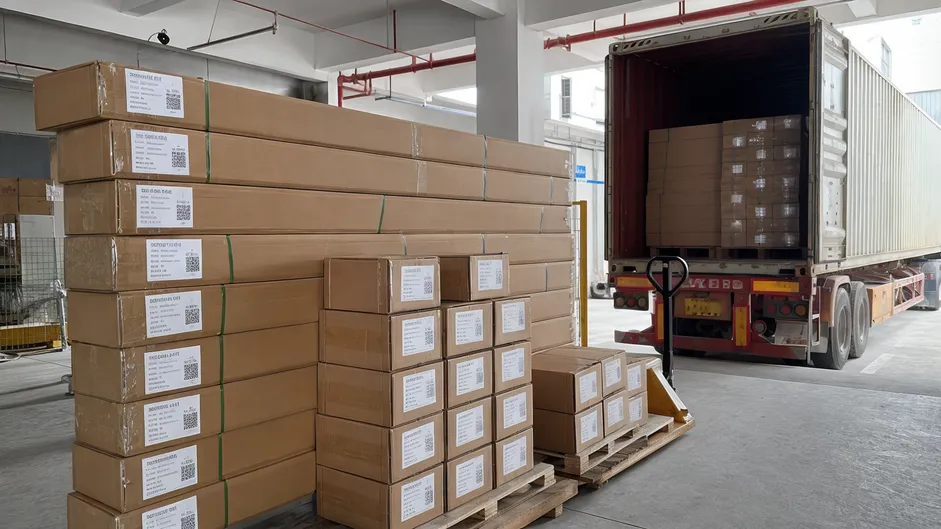
Need packing specs, UN38.3 documentation, or a loading plan for your order?
Smart Solar Pole or Another Smart Solar Lighting Product?
The four products in JXSOL's smart solar lighting range serve different procurement needs. Use the table below to confirm you're on the right page — or find the product that better fits your project.
| Product | Best Fit | When to Choose |
|---|---|---|
|
Smart Solar Poles This page |
Municipal streetscape, campus, industrial park, smart-city infrastructure |
You need an integrated pole system where the pole is the product — visual integration, structural engineering, and system-level QC matter |
|
Road, pathway, parking, and campus lighting where pole design is not the primary requirement |
You need reliable autonomous solar lighting and the pole is a standard mounting structure, not a design element |
|
|
Large installations needing centralized control, or OEM buyers integrating a specific control architecture |
You need the controller and communication layer — remote monitoring, group dimming, IoT platform integration — as the primary product |
|
|
Security-driven projects: perimeter lighting, parking surveillance, remote site monitoring |
Surveillance is a primary requirement alongside lighting — one pole, one power source, one installation |
Smart Solar Poles
This pageBest Fit
Municipal streetscape, campus, industrial park, smart-city infrastructure
When to Choose
You need an integrated pole system where the pole is the product — visual integration, structural engineering, and system-level QC matter
Best Fit
Road, pathway, parking, and campus lighting where pole design is not the primary requirement
When to Choose
You need reliable autonomous solar lighting and the pole is a standard mounting structure, not a design element
Best Fit
Large installations needing centralized control, or OEM buyers integrating a specific control architecture
When to Choose
You need the controller and communication layer — remote monitoring, group dimming, IoT platform integration — as the primary product
Best Fit
Security-driven projects: perimeter lighting, parking surveillance, remote site monitoring
When to Choose
Surveillance is a primary requirement alongside lighting — one pole, one power source, one installation
Not sure which product fits your project? Send your project parameters to our team and we'll recommend the right configuration.
Smart Solar Poles FAQ for Project Buyers
Answers to the specification and procurement questions that come up most often when buyers are sizing a smart solar pole project for the first time.
What pole height is typical for smart solar poles?
The most common range is 6m–10m for road and streetscape applications. The pole height determines the LED power requirement, the solar panel wattage, and the wind load calculation — so it's the first parameter we need to confirm when sizing a project.
| Pole Height | Typical Application | Road Width |
|---|---|---|
| Below 6m | Pathway and amenity lighting in parks and resort areas | — |
| 6m | Residential roads, pathways, campus walkways | 6–8 m |
| 8m–10m | Main roads, industrial park perimeter roads, campus main routes | 10–14 m |
How is the battery accessed for maintenance on a smart solar pole?
The battery compartment is built into the pole body at 0.8–1.2 meters above ground level, with a lockable IP65-rated access panel. A technician can open the panel, disconnect the battery pack, and replace it without removing the pole or using a ladder. The controller is mounted inside the same compartment on a DIN rail bracket.
LiFePO4 Battery Service Window
For LiFePO4 batteries with a 2,000+ cycle life, battery replacement is typically not needed within the first 5–7 years of operation. When replacement is eventually required, the access panel design makes it a straightforward field operation — not a pole removal job.
Can a smart solar pole support a camera or IoT communication module?
Yes. IoT communication modules (4G, NB-IoT, Zigbee, LoRa) are integrated into the controller compartment, with the antenna routed to the exterior through a sealed port. Camera modules (2MP–4MP, IP67-rated) can be mounted on the pole body or fixture arm, with the cable routed through the pole interior to the controller.
IoT Communication Modules
- 4G / LTE
- NB-IoT
- Zigbee
- LoRa
Camera Module Specs
- 2MP–4MP resolution
- IP67-rated enclosure
- Pole body or fixture arm mount
- Internal cable routing to controller
Power Budget: Resize Before Adding a Camera
A camera adds 3–8W of continuous draw to the system. This must be accounted for in the battery and solar panel sizing. We calculate the combined LED + camera + communication load when configuring the system. Buyers who add a camera to a standard solar pole specification without resizing the battery often find the system cannot sustain both loads through a cloudy week.
For projects where camera integration is a primary requirement, see also: Solar Street Light With Camera
What information is needed to size the battery and solar panel for a smart solar pole project?
The minimum inputs are: installation latitude (or country and city), LED power requirement or target lux level, operating hours per night, required autonomy nights, and whether the pole includes a camera or IoT module. From these we calculate the battery capacity and solar panel wattage.
We size the solar panel to the winter solstice irradiance at the installation latitude — not the annual average — because a panel sized for summer irradiance will underperform in winter and the battery state of charge will drop progressively over consecutive cloudy days.
If you have a project spec sheet or a competitor's product you're trying to match, send it — that's a normal starting point.
Minimum sizing inputs required:
Sizing note: We use winter solstice irradiance at the installation latitude — not the annual average — to ensure the system performs through the worst-case seasonal period.
What IP rating should smart solar pole lighting use for outdoor projects?
IP65 is the minimum for the LED fixture and solar panel junction box — it protects against dust ingress and water jets from any direction. Requirements step up depending on the component and installation environment.
LED Fixture & Junction Box
Minimum standard. Protects against dust ingress and water jets from any direction.
Battery Compartment
IP67 required for coastal areas with salt spray, flood-prone sites, or where the access panel may be exposed to standing water.
Integrated Camera Module
Always IP67-rated for poles with integrated cameras. No exceptions.
We test every IP65/IP67 housing with positive air pressure after final assembly — not just a visual inspection or a sample test.
What is the MOQ for standard and customized smart solar poles?
Standard Catalog Models
Minimum order quantity
Covers standard pole heights (6m, 8m, 10m), standard powder coat colors, and standard LED/battery/panel configurations.
OEM programs with custom branding, powder coat color, and firmware only — no structural changes — also qualify for the 100-unit MOQ.
OEM/ODM Custom Specifications
Typical minimum order quantity
Applies to modified pole cross-section, non-standard battery compartment size, custom panel mounting configuration, or structural changes.
Exact MOQ depends on the scope of tooling or component changes required. Engineering review is included in the OEM process.
Engineering review is included in the OEM process regardless of order scope. If you have a project spec sheet or a competitor's product you're trying to match, that's a normal starting point for the review.
Request a Smart Solar Pole Quote With the Right Inputs
A useful quote for smart solar poles requires more than a pole height and quantity. The configuration — battery capacity, solar panel wattage, structural specification, controller firmware, communication module — depends on your project parameters. Send us the following and we'll come back with a specific configuration recommendation and a detailed quote.
Project Parameters to Include
-
Country and installation latitude
For solar irradiance and autonomy sizing
-
Project type
Municipal road, campus, industrial park, resort, smart-city pilot
-
Pole height
Or target mounting height if not yet confirmed
-
Road or path width
For LED power and optic selection
-
Target lux level
If specified in the project tender or brief
-
Operating schedule
Hours per night, dimming profile, motion-sensor requirement
-
Autonomy nights required
Consecutive cloudy days the system must sustain
-
IoT or camera requirement
Communication protocol, camera resolution, monitoring platform
-
Order quantity
For standard or OEM/ODM pricing
-
Certification market
CE for Europe, or other market-specific requirements
-
Branding requirement
Standard JXSOL, private-label, or OEM
Contact JXSOL
We review project parameters and return a specific configuration recommendation — not a generic price list. Typical response within one business day.