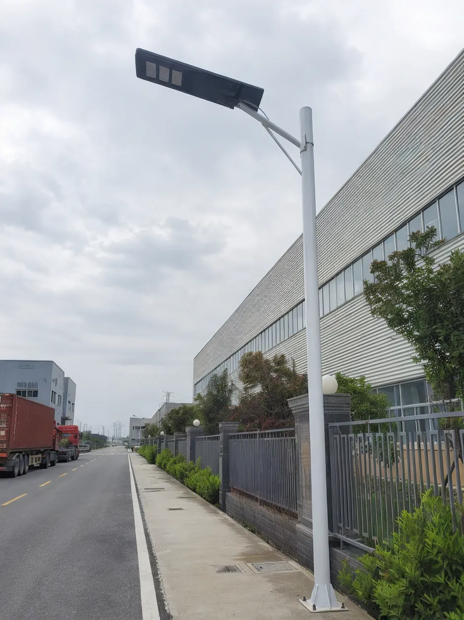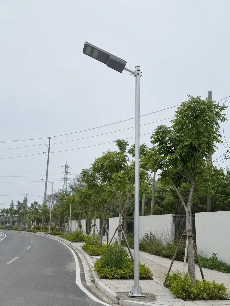
The Solar Panel Is Not an Accessory in Wind Design
A contractor approves a solar highway lighting package based on a pole wind rating in the supplier catalog. The project later increases panel wattage to meet autonomy requirements — larger panel, heavier bracket. The poles go up along an open coastal highway. After the first storm season, several lean. A few bracket welds crack. The supplier points to the pole rating. The installer points to the foundation. The buyer pays for replacement units, lane closures, and rework.
This is not a rare scenario. We see the pattern in field feedback from projects across the Middle East and Southeast Asia: the pole rating was real, but it applied to a different configuration than what was actually installed.
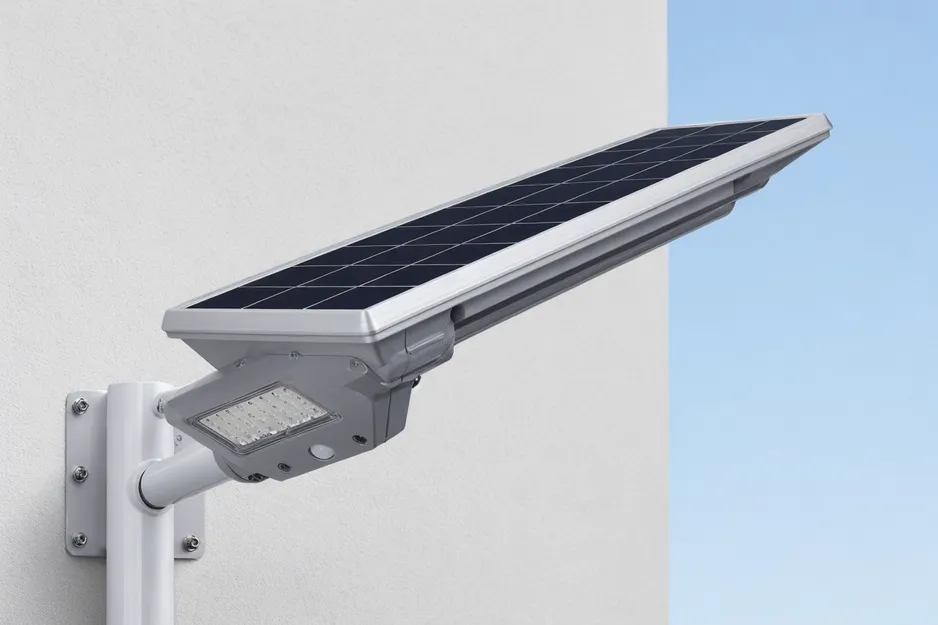
The core problem is that a solar highway light is structurally different from a grid-powered highway light. A grid pole carries a luminaire and arm. A solar highway light adds a solar panel, a mounting bracket, sometimes a battery housing, and a top-mounted assembly that can be significantly larger than the luminaire itself. That panel becomes a wind-catching surface — a sail — and the pole calculation changes accordingly.
Red flag: A supplier provides a wind rating without specifying what panel size, pole height, tilt angle, or standard it applies to.
Red flag: A solar highway light is quoted on the same pole table as a grid highway light, with no adjustment for the panel assembly.
IP65, IP67, CE, RoHS, and electrical performance documents confirm weatherproofing and electrical compliance. None of them replace structural wind verification. A solar street light wind load rating is only useful when it applies to the full installed system: pole, arm, luminaire, solar panel, bracket, anchor bolts, base plate, and foundation assumptions. Getting that specification right before the order is locked is the only way to protect project margin and keep warranty exposure under control.
Wind Zone First, Product Catalog Second
The specification process for a solar highway light wind load starts at the installation site, not the supplier catalog. Buyers who start from the catalog and work backward to the site conditions are the ones who end up with mismatched configurations.
Before you can ask a supplier to confirm structural adequacy, you need to define the site:
- Design wind speed from the applicable project code — not average weather data, not historical storm records. The design wind speed is a code-defined value that accounts for return period and exposure. In the US, ASCE 7 defines wind speed maps by risk category. In Europe, EN 40 governs lighting column structural design. Most road authorities in the Middle East, Southeast Asia, and Africa reference either a national building code or a regional road standard that specifies design wind speed by zone.
- Exposure category or terrain condition — open terrain, coastal, mountain pass, bridge deck, or elevated road section. An open coastal highway corridor can see effective wind pressures 30–50% higher than a sheltered urban street at the same nominal wind speed, because there is no upstream obstruction to reduce gust intensity.
- Pole height and mounting location — wind pressure increases with height, and the overturning moment at the base increases with the square of the height above ground.
- Road authority requirements — some jurisdictions require stamped structural calculations for highway lighting poles regardless of the supplier's catalog rating.
Check: Pull the design wind speed from the project code, not from a weather website. Average annual wind speed and design wind speed are different numbers.
Check: Identify whether the corridor is open terrain, coastal, bridge, or elevated. These conditions change the effective wind pressure on the pole and panel assembly.
Red flag: An RFQ that says only "high wind area" with no wind speed, applicable code, pole height, or exposure condition. A supplier cannot confirm structural adequacy from that description.

How the Solar Panel Changes the Pole Calculation
This is the part most catalog wind ratings skip, and it is where most procurement mistakes happen.
Wind load on a pole structure is calculated from the effective projected area of everything mounted on the pole — luminaire, arm, panel, bracket, and any housing — multiplied by the wind pressure at that height. A standard grid highway light has a relatively small projected area at the top: the luminaire and arm. A solar highway light adds the panel face, which on a 200W–400W fixture can be 0.8 m² to 1.6 m² of additional projected area, mounted on a bracket that extends away from the pole centerline.
That bracket offset matters. The further the panel center of mass sits from the pole axis, the larger the bending moment it generates at the base under wind load. A panel mounted 600 mm off-center on a 10 m pole creates a meaningfully different base moment than the same panel mounted flush against the pole. Panel tilt angle also changes the exposed area: a panel tilted at 15° presents a different projected area to horizontal wind than one tilted at 30°.
The table below shows what data the buyer needs to provide for each component, and what can fail if it is left unspecified:
| Component | Data buyer should provide | What can fail if ignored |
|---|---|---|
| Solar panel | Length, width, tilt angle, mounting bracket offset from pole centerline | Underestimated projected area, incorrect overturning moment |
| Luminaire | Weight, dimensions, arm length | Arm fatigue, weld cracking at arm-to-pole joint |
| Battery housing | Position (top-mounted vs. pole-integrated), weight | Shifted center of gravity, increased base moment |
| Pole | Height, diameter, taper, wall thickness, material grade | Pole lean, base plate cracking, anchor bolt pull-out |
| Bracket | Thickness, weld spec, fastener grade | Bracket deformation, weld failure at panel mount |
| Foundation | Anchor bolt pattern, embedment depth, concrete grade | Anchor bolt pull-out, base plate rocking |
Integrated designs — where the battery is inside the pole or the panel is fixed directly to the luminaire housing — still need the same review. The geometry is different, but the calculation logic is the same: total projected area, mounting height, bracket offset, and base moment.
Red flag: A supplier confirms luminaire wind resistance but does not include the panel bracket in the calculation basis.
Red flag: Panel wattage is increased late in the project — for autonomy reasons — without recalculating the pole. A 100W panel and a 300W panel are not structurally interchangeable on the same pole at the same height.
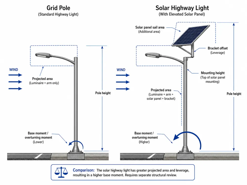
Step-by-Step: Building a Usable Wind Load Specification
This is the workflow we walk buyers through before locking a production order. It is not a structural engineering course — it is a procurement sequence that prevents the configuration mismatches that cause field failures.
Step 1: Confirm local design wind speed and applicable standard. Pull the design wind speed from the project code. For US highway projects, ASCE 7 wind speed maps by risk category. For European projects, EN 40 governs lighting column design. For other markets, identify the national building code or road authority standard that applies. If the project engineer has already specified a design wind speed, use that number directly.
Step 2: Fix pole height, road geometry, and lumen target. Pole height determines the wind pressure at the top of the pole and the overturning moment at the base. Road width and spacing determine the number of poles and the lumen distribution requirement. Lock these before selecting a fixture, because changing pole height after structural confirmation requires recalculation.
Step 3: Define the full top-of-pole assembly. This is where most buyers underspecify. You need: solar panel wattage and physical dimensions, panel tilt angle, bracket type and offset from pole centerline, luminaire weight and dimensions, arm length, and battery housing position. If you are evaluating Solar Highway Lights from multiple suppliers, get the panel and bracket dimensions for each configuration — they are not the same across models.
Step 4: Estimate effective projected area as a screening step. You do not need a licensed engineer to do a rough check. Add the panel face area (adjusted for tilt) to the luminaire and arm projected area. If the combined projected area is significantly larger than a standard grid luminaire, the pole needs a separate structural review — not the catalog rating.
Step 5: Confirm pole structure with supplier engineering. Provide the site wind speed, exposure condition, pole height, and full top-of-pole assembly dimensions. Ask the supplier to confirm pole diameter, taper, wall thickness, material grade, base plate dimensions, anchor bolt pattern, and foundation assumptions. This is a highway solar light structural specification review, not a catalog lookup.
Step 6: Freeze drawings and BOM before production. Once the structural review is complete and the configuration is confirmed, lock the drawings and bill of materials. Any change to panel size, pole height, or bracket geometry after this point requires a new review. We hold this line on every OEM order — a drawing freeze before component procurement is the only way to prevent rework.
Red flag: A supplier quotes pole wall thickness before seeing panel dimensions. Wall thickness is an output of the calculation, not a starting assumption.
Red flag: A buyer changes pole height or panel wattage after structural confirmation without requesting a revised review.
What Makes a Wind Load Claim Usable
"Wind resistant up to 150 km/h" on a catalog page is not a specification. It is a marketing claim until it is tied to a named standard, a defined design wind speed, an exposure condition, and a specific system configuration.
A usable solar street light wind load rating includes:
- The applicable standard (ASCE 7, EN 40, or the relevant national code)
- The design wind speed and return period
- The exposure category or terrain condition
- The pole height, diameter, taper, and wall thickness assumed in the calculation
- The panel size, tilt angle, and bracket geometry included in the projected area
- The base plate dimensions and anchor bolt pattern
- The foundation assumptions (concrete grade, embedment depth, soil bearing capacity)
IEC 62124 is worth clarifying here. It is a solar photovoltaic system performance standard — it covers electrical output, battery charge/discharge behavior, and system autonomy. It does not certify pole structural adequacy or wind load resistance. CE marking covers electrical safety and EMC compliance for the fixture. Neither document replaces a structural wind load calculation for the pole and foundation system.
The documents you should request from a supplier before approving a highway solar light structural specification:
- Product drawing with dimensions and weights
- Pole drawing with diameter, taper, wall thickness, and material grade
- Panel bracket drawing with offset dimensions and weld spec
- Anchor bolt layout drawing
- Material specification for pole steel
- Base plate and weld notes
- Calculation sheet or structural review basis
- Foundation assumptions document
Red flag: The wind rating is supported only by a catalog line or a marketing page. No drawing, no standard, no calculation basis.
Red flag: The supplier cannot identify the standard or the configuration assumptions behind the number they quoted.
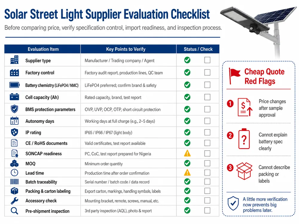
Supplier Verification Checklist Before Purchase Approval
Before approving a pole-fixture combination for a high-wind corridor project, work through these questions with the supplier. Each one connects to a specific failure mode or commercial risk.
On the rating basis:
- What design wind speed and standard is the rating based on?
- What exposure category or terrain condition was assumed?
- Does the rating apply to the full pole-fixture-panel assembly, or only to the pole alone?
On the panel and bracket:
- Does the calculation include the exact solar panel size and tilt angle for this order?
- What is the bracket offset from the pole centerline?
- What bracket wall thickness and weld specification are used?
On the pole structure:
- What pole height, diameter, taper, wall thickness, and material grade are assumed?
- Is the pole hot-dip galvanized or painted? What is the coating thickness?
- What base plate dimensions and anchor bolt pattern are specified?
On the foundation:
- What foundation assumptions are included — concrete grade, embedment depth, soil bearing capacity?
- Are the anchor bolts treated as part of the structural package, or supplied separately?
On change control:
- What configuration changes trigger a recalculation before production?
- If panel wattage increases, does the supplier automatically flag the structural impact?
Tying each of these to commercial value: a supplier who can answer all of them reduces your warranty exposure, eliminates emergency freight for replacement poles, and gives your project approval package a defensible structural basis. A supplier who cannot answer them is transferring that risk to your project margin.
For a complete review of road lighting system options and configurations, see Solar Street & Roadway Lights Manufacturer.
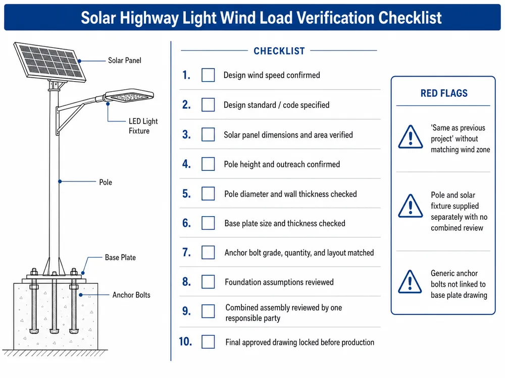
Red flag: The supplier says "same as previous project" without confirming that the wind zone, pole height, and panel size match.
Red flag: The pole and solar fixture come from separate suppliers with no single party reviewing the combined assembly. This is more common than it should be on price-driven tenders.
Red flag: Anchor bolts are treated as generic accessories and sourced separately without reference to the pole base plate drawing.
Specification Mistakes That Become Field Failures
These are the patterns we see repeatedly in projects that come back with structural problems. None of them are exotic engineering failures — they are procurement decisions that looked reasonable at the time.
Using average wind speed instead of design wind speed. Average annual wind speed for a region might be 6–8 m/s. The design wind speed for the same region under ASCE 7 or a local road code might be 40–50 m/s for a 50-year return period. These are not the same number, and using the wrong one produces a pole that is structurally inadequate for the actual risk environment.
Ignoring corridor exposure. An open coastal highway, a bridge deck, or an elevated road section has no upstream obstruction to reduce gust intensity. The effective wind pressure on the pole and panel assembly in these locations is higher than a standard urban street at the same nominal wind speed. Buyers who specify from a city-average wind zone without checking corridor exposure are underspecifying the structure.
Increasing panel wattage for autonomy without checking structural load. This is the most common late-stage mistake. The project autonomy calculation comes back short, so the panel wattage goes up — from 200W to 300W, or from 300W to 400W. The panel gets physically larger. The bracket gets heavier. Nobody rechecks the solar pole wind load calculation. The poles go up with a configuration that was never structurally reviewed.
Reducing pole wall thickness to cut freight cost. Thicker pole walls add weight, which adds freight cost. On a 500-unit order, the difference between a 3.5 mm and a 4.5 mm wall thickness is real money in a container. But wall thickness is a structural output, not a cost lever. Reducing it without recalculating the pole for the actual wind load and panel configuration is how you get pole lean after the first storm season.
Treating foundation design as separate from pole approval. The anchor bolt pattern, embedment depth, and concrete grade are part of the structural system. A pole that is correctly sized for the wind load can still fail if the foundation is undersized or if the anchor bolts are generic hardware that was not specified to match the base plate. Foundation assumptions should be part of the supplier's structural review, not a separate civil engineering afterthought.
Skipping drawing freeze before mass production. Configuration changes after production starts — a different panel bracket, a revised arm length, a substituted pole supplier — can invalidate the structural review without anyone flagging it. A drawing freeze before component procurement is the control point that prevents this.
Red flag: Price comparison focuses only on pole weight per kilogram and ignores the cost of a field failure: replacement labor, lane closure, warranty dispute, and project delay.
What to Send for Engineering Confirmation Before the Order Is Locked
We do structural review as part of the OEM/ODM process — it is not a separate service or an add-on. But the review is only as good as the data we receive. Here is what the engineering team needs to confirm a highway solar light structural specification before production:
- Project country or region — to identify the applicable standard and wind zone map
- Design wind speed — from the project code or road authority requirement, in m/s or km/h
- Applicable standard — ASCE 7, EN 40, or the relevant national code
- Road type and corridor condition — open terrain, coastal, bridge, elevated, or urban
- Pole height — in meters, from ground to luminaire mounting point
- Fixture power and lumen target — to confirm the luminaire size and weight
- Solar panel wattage and physical dimensions — length, width, and tilt angle
- Battery housing position — top-mounted, pole-integrated, or separate ground cabinet
- Installation quantity — for production planning and component procurement
- Road authority drawing requirements — if stamped calculations or specific drawing formats are required for project approval
With this data, we can confirm pole diameter, wall thickness, taper, base plate, anchor bolt pattern, and bracket design before any component is ordered. The structural review is done in-house — not outsourced to a third-party calculation service — because the engineers who review the pole are the same team that specifies the bracket weld and the anchor bolt grade. That connection matters when a project has a non-standard corridor condition or a tight approval timeline.
(We have seen projects where the buyer sent only lumen output and quantity. That is enough to quote a price, but not enough to confirm structural adequacy. The structural data needs to come with the RFQ, not after the PO is signed.)
If your project has a defined wind zone, pole height, and panel configuration, Request Quote with that data and the engineering team will include a structural specification with the commercial quote.
Buyer Questions That Deserve Short Answers
Can one solar street light wind load rating apply to every project?
No. A wind load rating is configuration-specific. It applies to a defined pole height, panel size, tilt angle, bracket geometry, and design wind speed. Change any of those variables and the rating no longer applies. A supplier who quotes a single wind rating for all projects without asking for site data is not doing a structural review — they are repeating a catalog number.
Does a thicker pole always solve wind resistance problems?
Not automatically. Wall thickness is one variable in the structural calculation. Pole diameter, taper, material grade, base plate dimensions, anchor bolt pattern, and foundation assumptions all contribute to the system's ability to resist wind load. Increasing wall thickness without reviewing the full system can add freight cost without addressing the actual failure mode — which is often at the bracket weld, the base plate, or the anchor bolt embedment.
Does IP65, IP67, CE, or IEC 62124 prove solar highway light pole wind resistance?
No. IP ratings confirm ingress protection against dust and water. CE marking covers electrical safety and EMC compliance. IEC 62124 covers solar photovoltaic system performance. None of these standards address pole structural adequacy or solar highway light pole wind resistance. Structural wind load verification requires a separate calculation based on the applicable structural standard for the installation jurisdiction.
Should integrated and split solar highway lights use the same wind load check?
Yes, with different inputs. An integrated design — where the panel is fixed to the luminaire housing — has a different projected area geometry than a split design with a separate panel on a side bracket. Both need a full system review: projected area, mounting height, bracket offset, pole structure, and foundation. The calculation method is the same; the input geometry is different. Do not assume an integrated design is automatically lower wind load — some integrated top assemblies are larger and heavier than a split panel on a compact bracket.