Why PIR Range and Detection Angle Matter for Solar Security Light Performance
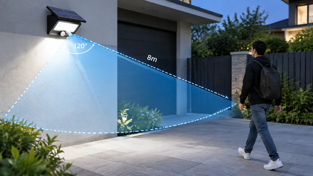
PIR range determines how far from the light a person must be to trigger illumination. Detection angle determines lateral coverage — the width of the zone the sensor monitors. Get either wrong and you're deploying units that either miss targets entirely or waste battery charge on false activations.
We see three deployment failures more often than any other: missed detection when range is too short for the mounting height, false triggers when angle is too wide and picks up heat sources outside the intended coverage zone, and dead zones when the sensor is angled toward empty space instead of the approach path. All three trace back to spec sheets that don't match field conditions or weren't verified before the container shipped.

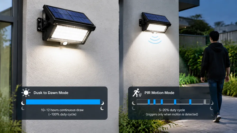
Unlike wired security lights where wasted triggers cost nothing but bulb life, solar lights lose battery charge with every activation. A PIR sensor tuned too aggressively can drain the battery before sunrise, leaving the light dark the next night. A sensor tuned too conservatively turns the product into decorative hardware that never activates when needed. PIR tuning directly affects runtime between charge cycles — not a secondary feature, the core operating constraint of any solar security light.
That's why verification matters before you commit to production quantities. A 12-meter range claim on a datasheet means nothing if the sensor triggers at 8 meters in your target market's temperature range or mounting configuration. You need verifiable specs, field test protocols you can run on samples, and documentation proving the factory tests detection function during production — not just assembly continuity.
Key PIR Specifications to Request from the Factory Before Ordering
Most PIR datasheets list detection range as a single number — "12 meters" or "8 meters" — without specifying the test conditions. That number is usually measured at sensor level with the target walking perpendicular to the beam at 20–25°C ambient temperature. Mount the same sensor 5 meters high, angle it downward 20°, and test it at 35°C, and effective range drops to 60–70% of the datasheet claim. Request range specifications that include ambient temperature, mounting height, and approach angle, or you're guessing.
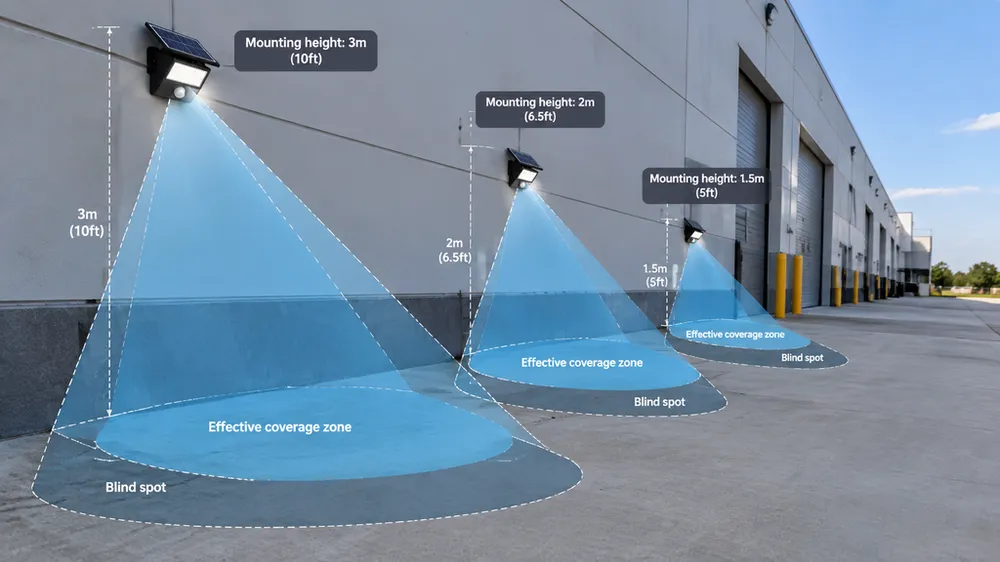
Detection angle matters in two dimensions: horizontal and vertical. A sensor with 120° horizontal coverage and 60° vertical coverage behaves very differently at 3-meter mounting height versus 6-meter height. Most datasheets only list horizontal angle because it's the larger number. Vertical angle determines how much ground coverage you get at distance — critical for high-mount parking lot or perimeter applications. Request both, and request the cone diagram if the factory has one (most don't publish it, but engineering teams generate them during product design).
Adjustability divides into three categories: fixed-angle sensors where the PIR module is permanently aligned during assembly, tilt-adjustable sensor heads that let installers reposition the detection zone in the field, and software-configurable sensitivity where the controller firmware can be tuned remotely or via DIP switch. Fixed-angle costs less and installs faster but locks you into one application type. Adjustable heads add $2–5 per unit but eliminate SKU proliferation when you're serving mixed installation scenarios. Software tuning is OEM/ODM territory — we offer it for orders over 500 units where the buyer wants site managers to adjust parameters without ladder access.
Lux threshold is the ambient light level below which the sensor becomes active. Standard setting is 10–20 lux, roughly equivalent to late dusk. That works for open sites. Shaded installations — under canopies, near building overhangs, or in high-latitude markets with extended twilight — need lower thresholds (5–10 lux) or the light won't activate until full dark, missing the early evening security window. Request the lux threshold value and whether it's adjustable. Most controllers use a fixed photoresistor value; custom firmware can change it.
Hold time is how long the light stays on after detecting motion. Standard hold times are 20–30 seconds. Pathway lights benefit from shorter hold (15–20 seconds) to avoid lighting empty paths. Parking lot and loading dock applications need longer hold (30–60 seconds) because people move slowly through the zone — vehicles parking, workers unloading. Non-adjustable timers are cheap but limit application flexibility. If you're quoting multiple site types, request adjustable hold time or plan to stock multiple controller variants.
Here's the RFQ checklist we recommend sending to factories:
Detection range: Specify range in meters at 20°C, 30°C, and 5°C if your target market sees temperature extremes. Request range at your intended mounting height, not sensor-level test conditions.
Detection angle: Request horizontal and vertical angles in degrees. Ask for the cone coverage diagram if available.
Adjustability: Confirm whether the sensor head is fixed-angle, tilt-adjustable, or software-configurable. If adjustable, request adjustment range and locking mechanism (some cheap adjustable heads drift after wind exposure).
Lux threshold: Request the activation lux value and whether it's field-adjustable or firmware-configurable.
Hold time: Request on-duration in seconds and whether it's adjustable. If adjustable, request the range (e.g., 10–90 seconds).
Test documentation: Request evidence the factory tests PIR function during production. Photos of test benches or QC procedure documents work. Most factories only test "does it turn on at night" — you want confirmation they verify detection distance and response time.
How to Verify PIR Range Claims with Field Testing
Spec sheet claims reflect lab conditions: controlled temperature, calibrated heat sources, perpendicular approach angles. Field performance depends on mounting height, ambient temperature, target heat signature, and approach vector. A sensor rated for 12 meters might trigger at 10 meters when mounted 5 meters high or at 8 meters in 35°C heat (PIR sensitivity drops as ambient temperature approaches body temperature). Verification requires field testing samples under your actual deployment conditions before committing to container quantities.
The simplest field test protocol: mount a sample at the intended height, block the solar panel to simulate night (or test after dark), walk toward the sensor from known distances marked with tape or cones, and note the trigger distance. Repeat from multiple approach angles — head-on, 45° diagonal, and 90° tangential. PIR sensors detect motion across detection zones, not motion toward the sensor, so tangential approaches often trigger at shorter effective range than head-on approaches. If your installation puts the approach path at an angle to the sensor face, test that angle specifically.
Temperature matters. If your deployment site experiences temperature extremes — over 35°C in summer or below 5°C in winter — test at those conditions or request factory data showing sensitivity degradation curves. PIR sensors work by detecting temperature differentials between the target and background. When ambient temperature is 35°C and body temperature is 37°C, the differential is too small for reliable detection beyond 60–70% of rated range. When ambient is 5°C and body temperature is still 37°C, the differential is large and detection range can exceed datasheet claims. Most solar security light failures in Middle East markets trace back to this — buyers assume 12-meter range will work in 40°C heat and it doesn't.
Mounting height and downward angle compress effective range because you're detecting the target at an oblique angle, not perpendicular. A sensor mounted 5 meters high and angled downward 20° to cover a pathway doesn't see a person until they're 2–3 meters closer than the horizontal range spec suggests. The trigonometry works out to roughly 0.6× rated range for 5-meter mounting height with 20° downward angle. For 3-meter mounting height with 15° downward angle, multiply rated range by 0.75. Most buyers don't account for this and then blame the sensor.
If factory claims 12-meter range and your field test triggers at 8 meters, the discrepancy is often mounting height or vertical detection angle mismatch, not sensor defect. Before rejecting samples, confirm you're testing at the same conditions the factory specified. If they rated range at sensor level (0-meter mounting height, horizontal aim) and you're testing at 5-meter mounting height with downward angle, your 8-meter result might be exactly what the spec predicts. Request the factory's test conditions in writing so you know what the baseline is.
Matching PIR Range and Angle to Installation Scenarios
Detection specs that work for a parking lot perimeter don't work for a building entrance, and pathway specs don't work for a loading dock. Range and angle must match mounting height, coverage area, and approach path — otherwise you're either underlighting the zone or triggering on irrelevant motion outside it.
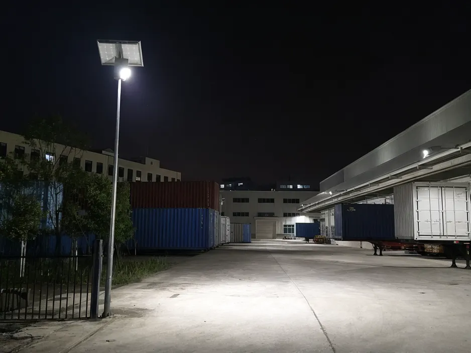
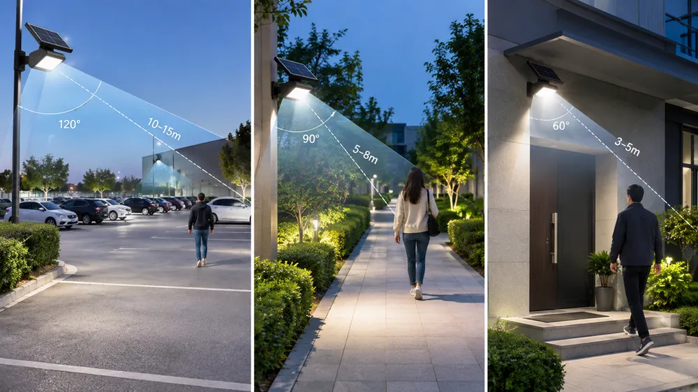
Parking lot perimeter (mounting height 5–6 meters): You need 120–150° horizontal angle and 10–12-meter range with the sensor head angled downward to cover the lot edge before people reach parked vehicles. Wide horizontal angle is critical because vehicles park at unpredictable locations; you're trying to cover a strip 20–30 meters wide per light. Vertical angle matters less here because the mounting height naturally compresses the detection cone. Fixed-angle sensors work if every pole is the same height, but if you're retrofitting mixed infrastructure, adjustable heads avoid height-dependent dead zones.
Building entrance or loading dock (mounting height 3–4 meters): 90–110° horizontal angle, 6–8-meter range, slightly angled toward the approach path. Narrower angle reduces false triggers from passing traffic or vehicle movement in adjacent lanes. You want the light to activate when someone approaches the door, not when a truck drives by 15 meters away. Hold time should be 30–60 seconds for loading docks because workers linger while unloading — 20-second hold times meant for pathways will leave them in the dark mid-task.
Pathway or sidewalk (mounting height 3–3.5 meters): 90° horizontal angle, 5–6-meter range, downward focus. Avoid wide angles that pick up lawn or foliage movement — wind-blown bushes 10 meters away don't need to trigger pathway lights. Tighter angles and shorter range keep activation relevant to people actually using the path. If you're spacing lights 8–10 meters apart along a pathway, 6-meter range gives you overlap without gaps, and 90° angle keeps detection centered on the walkway instead of spilling into landscaping.
Perimeter or fence line (mounting height 4–5 meters): 180° horizontal angle if corner-mounted, 8–10-meter range, adjustable head for site-specific calibration. Perimeter applications are the hardest to standardize because approach paths vary by site layout. Corner-mounting with 180° coverage eliminates one pole but requires careful vertical angle adjustment to avoid dead zones directly under the light. Straight fence-line mounting with 120° angle works if poles are evenly spaced, but any gaps in the fence line or irregular terrain need adjustable heads to compensate.
Here's the scenario-spec matching summary:
| Application | Mounting Height | Horizontal Angle | Range | Adjustability |
|---|---|---|---|---|
| Parking lot perimeter | 5–6m | 120–150° | 10–12m | Fixed OK if standardized heights |
| Building entrance | 3–4m | 90–110° | 6–8m | Fixed OK for single-door applications |
| Pathway/sidewalk | 3–3.5m | 90° | 5–6m | Fixed OK if terrain is flat |
| Loading dock | 3–4m | 90–110° | 6–8m | Adjustable recommended for mixed-height bays |
| Perimeter/fence line | 4–5m | 120–180° | 8–10m | Adjustable required for irregular sites |
The pattern: higher mounting height needs longer range to compensate for angle compression, wider coverage areas need wider horizontal angles but risk false triggers, and any site with terrain variation or mixed mounting heights benefits from adjustable sensor heads even though they cost more per unit.
Common Causes of False Triggers and How to Prevent Them
False triggers waste battery charge and create complaint loops from site managers who assume the product is defective when it's actually responding to heat sources the spec didn't account for. PIR sensors detect temperature differentials, not physical motion — anything that emits or reflects infrared radiation can trigger activation if it enters the detection zone with enough temperature contrast to the background.
HVAC exhaust vents are the most common false trigger source in commercial installations. Rooftop condensers, kitchen exhaust fans, and furnace flues all emit hot air plumes that drift across detection zones when wind direction aligns with the sensor. A parking lot light mounted 15 meters from a building might false-trigger every time the HVAC cycles on if the exhaust vent is upwind and the sensor angle is wide enough to catch the plume. Solution: narrow the horizontal angle to exclude the vent, reposition the light, or (if the buyer controls the building) redirect exhaust ducting. Can't solve it with sensor adjustment alone if the site layout forces overlap.
Vehicle engine bays and exhaust systems trigger PIR sensors reliably — a car idling 10 meters away radiates enough heat differential to activate lights meant for pedestrian detection. Loading docks and parking lot installations need to account for this. If vehicles routinely pass through the detection zone without stopping, you need narrower angles or higher lux thresholds so the light only activates in low-light conditions when vehicle heat signatures matter less (headlights provide illumination during vehicle movement). If vehicles stop and park within the zone, false triggers become true triggers — the light should activate because someone is exiting the vehicle.
Heat-radiating metal surfaces in direct sun store thermal energy and release it after sunset. Corrugated metal siding, chain-link fences with metal posts, and dark-painted surfaces can stay 5–10°C above ambient for hours after sunset, creating moving heat signatures if wind causes surface temperature variations or if small animals walk across them. We've traced false trigger complaints to metal fence posts 8 meters from the light — as the post cools unevenly, the PIR sensor detects the temperature gradient shift and activates. Solution: mount the light so the detection zone doesn't include large metal surfaces, or reduce sensitivity if the controller allows adjustment.
Wind-blown foliage or fabric enters detection zones and triggers activation if the foliage itself is warmer or cooler than the background (leaves in sun are warmer; leaves in shade after sunset are cooler). Tree branches, flags, banners, and tarps are common culprits. The issue isn't the motion — it's the temperature differential between the moving object and the static background behind it. Solution: trim foliage outside the detection zone, narrow the sensor angle to exclude flag poles or banners, or mount the light higher so the detection cone clears low vegetation. Some buyers ask for desensitized sensors, but that reduces human detection range too — better to fix the site layout.
Small animals and insects trigger PIR sensors less often outdoors than indoors (insects don't generate enough heat differential in open air), but ground-level or low-mount pathway lights can pick up cats, raccoons, or rodents if the sensor is aimed close to the ground. Mounting height above 3 meters usually solves this because small animals don't register at distance. If you must mount lower (bollard lights, ground-level pathway fixtures), accept that occasional animal triggers are unavoidable or specify reduced sensitivity (which shortens human detection range as a tradeoff).
Mounting angle errors cause more false triggers than any sensor defect. Sensor pointed at the ground too close to the light housing creates a hot-spot detection zone — the ground directly under the light heats during the day and cools at night, and the temperature shift triggers activation. Sensor pointed at the horizon picks up distant heat sources (passing vehicles, building exhaust, animals) that shouldn't matter for the intended coverage area. Optimal downward angle is 15–25° depending on mounting height: 15° for 3-meter mounts, 20° for 4–5-meter mounts, 25° for 6+ meter mounts. Too steep and you lose range; too shallow and you pick up irrelevant heat sources.
This is why adjustable sensor heads matter for multi-site deployments. A fixed-angle sensor optimized for one site type will false-trigger or underperform at a different site. Adjustable heads let installers tune the angle to the actual environment, which eliminates 60–70% of false trigger complaints in our experience (the remaining 30% are environmental heat sources that can't be avoided without narrowing angle or relocating the light).
Fixed-Angle vs. Adjustable PIR Heads — When Each Makes Sense
Fixed-angle sensors cost less, install faster, and eliminate field tuning errors where an installer sets the angle wrong and creates dead zones. If you're deploying 500 identical units in a parking lot where every pole is 5.5 meters high and the coverage requirement is identical, fixed-angle sensors are the right choice. One SKU, bulk pricing, no installer training needed beyond "mount the light, aim it generally downward." False trigger risk is low because the site is uniform and you can specify the angle based on a single site survey.
Tilt-adjustable sensor heads add $2–5 per unit (depending on order quantity and adjustment mechanism quality) but eliminate SKU proliferation when you're serving mixed-height or multi-application sites. A distributor stocking lights for parking lots, pathways, building entrances, and loading docks would need four fixed-angle SKUs to cover those applications optimally. With adjustable heads, one SKU works for all four if the range and lux threshold are appropriate. The per-unit cost is higher, but inventory carrying cost and stockout risk are lower. Adjustability also reduces warranty claims from installation errors — if the light doesn't cover the intended zone, the installer adjusts the head instead of returning the unit.
Build quality matters for adjustable heads. Cheap ball-joint mechanisms drift after wind exposure or vibration (especially on pole-mounted lights in high-wind areas). Locking collars or friction-fit adjustments with metal threads hold position better than plastic snap-fits. We use aluminum adjustment brackets with nylon-insert lock nuts — adds $1.50 to unit cost but eliminates drift complaints. Buyers focused purely on landed cost often choose plastic adjustable heads and then deal with field complaints six months later when sensors have shifted out of alignment. Worth asking the factory what the adjustment mechanism is made of and whether it's been wind-tested.
Software-configurable sensitivity is the third option. The PIR sensor itself is fixed-angle, but the controller firmware lets you adjust detection sensitivity, hold time, and sometimes lux threshold via DIP switches or wireless command (if the light has IoT connectivity). This is OEM/ODM territory — we offer it for orders over 500 units where the buyer wants centralized tuning. A property management company with 50 buildings can deploy one SKU everywhere and tune each site remotely based on false trigger reports or tenant complaints. The controller cost premium is $8–12 per unit depending on connectivity requirements (DIP switch is cheaper than LoRaWAN or NB-IoT), so it only makes sense for buyers managing large deployments where field service visits are expensive.
When fixed-angle makes sense: single-application deployments, standardized mounting heights, uniform site conditions, cost-sensitive projects where every dollar per unit matters. When adjustable heads make sense: multi-application distributors, mixed-height infrastructure, sites with terrain variation, buyers who want one SKU for flexibility. When software tuning makes sense: large-scale managed deployments, buyers with in-house technical staff, IoT-enabled smart city projects where remote diagnostics justify the controller premium.
How JXSOL Tests PIR Function During Production
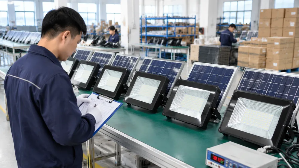
Most solar light factories test PIR function at final assembly as a pass/fail check: does the light turn on when you wave your hand in front of the sensor in a dark room? That confirms the sensor is connected and the controller responds, but it doesn't verify detection range, angle coverage, or response time against the datasheet spec. We run dedicated PIR sensor function test benches as part of in-process QC — not just final assembly spot-checks.
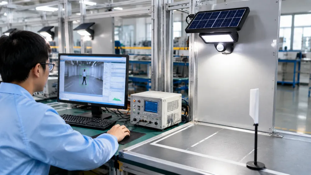
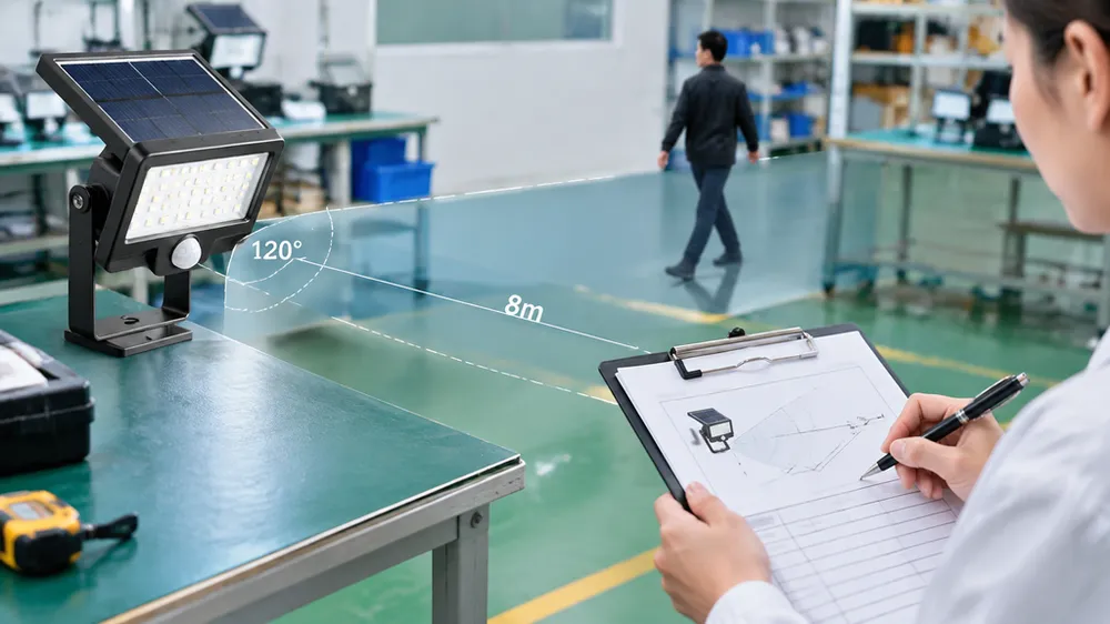
The test bench setup: calibrated infrared heat source mounted on a linear rail at sensor height, positioned at the detection range specified in the product datasheet (e.g., 8 meters for a pathway light, 12 meters for a parking lot fixture). The heat source simulates human body temperature (36–37°C surface temperature). We move the heat source across the detection zone at walking speed (1.2 m/s) and verify the controller activates the LED within 0.5 seconds. If response time exceeds 0.5 seconds or the sensor doesn't trigger, the unit is rejected.
We test detection angle by moving the heat source laterally at the rated range distance. A sensor spec'd for 120° horizontal angle must trigger when the heat source is 60° left or right of sensor centerline at rated range. Vertical angle is harder to test on a bench (requires height-adjustable rails), so we verify vertical coverage during product development and then rely on sensor component incoming inspection to catch defective PIR modules. Horizontal angle testing catches 80% of sensor defects; vertical angle failures are rare unless the sensor mounting bracket is misaligned during assembly, which we catch with a separate mechanical inspection step.
Controller and sensor are tested together because failures happen in both components. A defective PIR sensor won't trigger at rated range. A defective controller might not respond to the sensor signal, or might activate the LED but fail to hold it on for the programmed duration. Testing them as a system catches both failure modes. We also verify lux threshold by running the test under bright light (>100 lux) and confirming the controller doesn't activate — daylight lockout must work or the battery drains during the day.
Hold time verification: after the sensor triggers and the LED activates, we measure how long the light stays on without further motion detected. Standard hold time is 20–30 seconds depending on product spec. If the light turns off early or stays on indefinitely, the controller timer circuit is defective. This failure mode is uncommon (1–2 units per 1,000) but it's a warranty claim magnet because the product appears to work during installation and then behaves unpredictably in the field.
Testing depth like this is uncommon among solar light factories. Most rely on component supplier datasheets and test only final assembly continuity. We test in-process because PIR failures in the field cost more than in-process rejects — warranty claims, replacement logistics, customer trust. Buyers can request test bench photos or video as factory audit evidence. We send them routinely to project contractors who need QC documentation for bid submissions or to brand owners who want verification their OEM supplier isn't just hand-waving about testing rigor.
If you're comparing factories, ask what PIR testing they do and whether it's in-process or final assembly only. Ask for photos of the test setup. Ask whether they verify range, angle, and hold time or just "does it turn on." Most factories won't have dedicated benches — they'll describe a manual test procedure where a worker walks toward the light in a dark room and observes activation. That catches assembly errors but doesn't verify spec compliance. Bench testing with calibrated heat sources and measured distances is the difference between "we test PIR function" and "we verify PIR performance against datasheet claims."