Why Placement Determines Whether Your PIR Sensor Works or Wastes Power
A distributor in Texas ordered 200 solar motion flood lights for a warehouse perimeter project. Two weeks after installation, the site manager called: half the units weren't triggering when approached from the loading dock side, and three units near the HVAC exhaust fired every ten minutes all night. The units weren't defective — they were placed wrong.
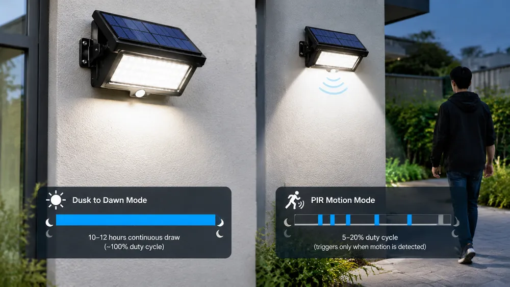
PIR sensors detect thermal contrast as an object moves across the detection field. If you mount the fixture too high or angle it incorrectly, the field doesn't intersect the approach path. The sensor works perfectly; it just isn't looking where you need it to look. Poorly placed units create two problems: security gaps where legitimate motion goes undetected, and false alarms that drain battery capacity and shorten service life. A unit that false-triggers twenty times per night instead of three real triggers will degrade battery chemistry 40-50% faster.
Correct solar motion sensor flood light placement aligned with the sensor's detection geometry reduces callbacks, extends operational lifespan, and lowers your total cost per installation year. For project contractors deploying 100+ units, placement errors compound into thousands of dollars in revisit labor and early replacements.
This guide explains PIR detection cone geometry, how mounting height affects effective range, false alarm root causes tied to component quality, and multi-unit layout logic for commercial perimeters and residential security projects. The goal is to help you spec unit count accurately, position fixtures for predictable coverage, and avoid the placement mistakes that turn good hardware into field complaints.
How PIR Detection Geometry Defines Effective Coverage Zones
PIR sensors don't emit a beam — they're passive infrared receivers. The sensor reads thermal contrast change across a detection cone defined by the Fresnel lens geometry molded into the sensor housing. Most residential and light-commercial solar flood lights use a 90° to 140° horizontal detection angle and a 60° to 90° vertical angle. The exact cone depends on the lens design; check your supplier's datasheet for the rated angle.
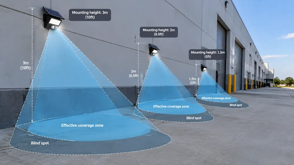
Detection range is almost always specified at an optimal mounting height, typically 2.5–3 meters for residential-grade units. If you mount higher, the horizontal range extends but the vertical field narrows, creating a blind zone directly below the fixture. At 5 meters, you might gain 14 meters of forward detection range, but anyone standing within 2 meters of the base will be invisible to the sensor.
Here's the relationship between mounting height and effective detection range for a typical 120° horizontal PIR module:
- 2.5m mounting height: 8m effective range, tight vertical field, minimal dead zone beneath fixture
- 3m mounting height: 10m effective range, moderate vertical coverage, suitable for most residential and small commercial applications
- 4m mounting height: 12m effective range, narrower vertical field, dead zone extends to ~1.5m radius below fixture
- 5m mounting height: 14m effective range, narrow vertical field, dead zone extends to ~2m radius — acceptable for perimeter intrusion detection where approach is always from distance
The flood beam angle and the sensor detection angle should align. If your flood optic produces a 120° beam and the PIR sensor has a 120° detection cone, the lit area matches the sensed area. If the flood beam is narrower (say, 90°), the edges of the detection zone will trigger lighting that doesn't actually illuminate the target — confusing for the person who triggered it and wasteful of battery. If the flood beam is wider than the sensor cone, the center of the approach path triggers correctly but the perimeter stays dark.

We've tested this relationship on production batches for OEM clients who deploy in both residential subdivisions (2.5m eave mounts) and industrial perimeters (4–5m pole mounts). The detection range numbers above are conservative estimates based on a 70kg adult crossing perpendicular to the sensor axis in still air at 20°C ambient. Cold weather tightens the range slightly because thermal contrast between body and background decreases; hot climates with direct sun on pavement can reduce daytime sensitivity by 15–20% due to background IR noise.
When you're sourcing for a specific project, verify two things in the supplier datasheet: the detection angle (horizontal and vertical) and the reference mounting height for the stated range spec. Some suppliers inflate range by testing at ground level or using unrealistic test conditions. If the datasheet doesn't state the mounting height for the range claim, ask for it. That's not a detail you want to discover during site commissioning.
Mounting Height Selection by Deployment Environment
Mounting height is a trade-off between coverage area per unit and detection zone control. Lower mounting gives you tighter control over where the sensor triggers; higher mounting covers more ground per fixture but requires multi-unit overlap planning to avoid gaps.
Residential perimeter (2.5–3m mounting height): This is standard eave height or fence-post height for most single-family and low-rise residential projects. At this height, the detection zone centers on pedestrian approach paths — driveways, side gates, backyard entries. The dead zone directly below the fixture is minimal (under 1 meter radius), so you don't lose coverage if someone walks close to the building. We recommend 2.5–3m for any application where you want the sensor to catch movement within 1–2 meters of the fixture, such as pathway lighting or garage entry points.
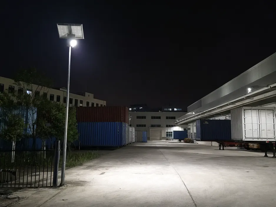
Commercial parking lots and warehouse perimeters (3.5–4m mounting height): This range balances vandalism resistance (harder to reach and tamper with), wider area coverage per unit, and vehicle-scale detection. At 4 meters, a 120° PIR sensor with 12m range covers roughly 200 square meters of detection area. The trade-off is the dead zone: if someone approaches directly beneath the pole, they won't trigger until they're 1.5–2 meters out. For perimeter fencing, that's acceptable because the threat approaches from outside the fence line, not from directly below. For parking lot aisles, you need to overlap sensor zones between adjacent units so no approach path falls into a combined dead zone. We've deployed this height for logistics centers in North America and Europe; typical spacing is 12–15 meters between poles for continuous coverage.
Perimeter fencing for storage yards, farms, and industrial sites (4–5m mounting height): Maximum mounting height for intrusion detection across long distances. At 5 meters with a high-quality PIR module, you can achieve 14+ meters of forward detection range, meaning fewer units per linear meter of fence. The dead zone directly beneath the fixture is 2+ meters, but that's not a concern if the fixture is mounted on the secure side of the perimeter and all approach paths cross the detection cone from outside. This height works well for solar flood lights on perimeter poles where the priority is detecting movement before it reaches the fence, not after someone is already inside the yard. One caution: wind load increases significantly above 4 meters, so verify the pole and fixture mounting bracket can handle local wind speed codes.
Pathway and garden accent lighting (2–2.5m mounting height): Lower mounting for close-range triggering in areas where you want selective activation. At 2 meters, detection range drops to 6–8 meters, but the sensor ignores movement beyond that distance. This reduces false alarms from street traffic, neighboring properties, or animals passing at a distance. We use this height for residential garden path projects and hospitality landscape lighting where the goal is "light the path when someone is on the path," not "light the entire yard."
For orders over 100 units where site layout matters — say, a contractor equipping a new housing development or a distributor supplying a commercial campus — our engineering team can review the site plan and recommend unit count, mounting height, and fixture spacing. That service costs nothing and reduces your risk of over-ordering or under-coverage. The typical failure mode we prevent is a buyer who calculates unit count based on the maximum rated detection range without accounting for mounting height, dead zones, or overlap requirements, then discovers gaps during commissioning.
Angle and Orientation to Eliminate Blind Spots
PIR sensors are most sensitive to motion across the detection field, not toward the sensor. An object moving perpendicular to the sensor axis (crossing left to right or right to left) generates strong thermal contrast change across multiple detection zones inside the Fresnel lens. An object approaching head-on along the sensor axis generates weak signal because it crosses fewer zones. This is why corner placement outperforms center-wall placement for rectangular perimeters.
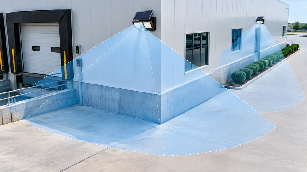
Corner-mount principle: Position fixtures at corners so target approach paths cross the detection cone at 45° to 90°, not head-on. For a rectangular warehouse or storage yard, place units at the four corners aiming along the walls, not at the center of each wall aiming outward. This setup ensures that anyone approaching the perimeter crosses at least one sensor's field at a strong angle. Center-wall placement forces head-on approaches from two directions, which the sensor may miss or detect late.
Avoid aiming at heat sources: HVAC exhaust vents, parked vehicles (especially engine hoods or exhaust pipes), and metal surfaces in direct sun all emit infrared radiation that can false-trigger low-quality PIR sensors. If your site layout requires mounting near these sources, angle the sensor away or specify units with adjustable sensitivity so you can reduce gain in the direction of the heat source. We've had OEM clients request sensitivity mapping for units deployed near industrial equipment; our engineering team can configure sensors with directional sensitivity reduction (lower gain on one side of the detection cone) for custom orders starting at 500 units.
Tilt angle for ground-level coverage: Most residential and light-commercial solar flood lights should tilt downward 10° to 15° from horizontal. This centers the detection zone at ground level 5–8 meters away. If you mount the fixture perfectly level, the detection cone centers too high and you lose sensitivity to low approaches (children, animals, or someone crouching). The built-in tilt adjustment on the mounting bracket is there for this reason — use it. For higher mounts (4+ meters), increase the downward tilt to 15°–20° to keep the detection zone footprint on the ground at the target distance.
Multi-unit overlap for continuous perimeters: If you're covering a 30-meter fence line with 10-meter-range sensors, don't space units exactly 10 meters apart. Real-world detection range varies with temperature, sensor calibration tolerance, and approach angle. Plan 20–30% overlap between adjacent zones. For a 10-meter sensor, that means 7–8 meter spacing. Yes, you'll use more units, but you'll eliminate the gaps that appear when one sensor is at the low end of its tolerance range or when mounting installation isn't perfectly aligned. This is standard practice for commercial security projects; it's less common in residential installs, but we recommend it for any perimeter where detection reliability matters more than minimizing unit cost.
One field detail worth noting: if your installation uses thin-wall conduit or sheet-metal poles, wind vibration can false-trigger the sensor. PIR modules detect motion via a pyroelectric element mounted on a flexible substrate; mechanical vibration can mimic thermal movement. We've seen this in coastal installs and high-wind agricultural sites. The fix is solid mounting — either a rigid pole (schedule 40 steel pipe, not thin EMT conduit) or a vibration-damping washer between the fixture and the bracket. It's a $2 part that eliminates a chronic false alarm source.
False Alarm Root Causes Tied to Component Quality and Placement
False alarms fall into two categories: placement errors and component quality issues. Placement errors — aiming at heat sources, mounting on vibrating surfaces, positioning where foliage blows across the field — you can fix in the field. Component quality issues require better sourcing decisions upfront.
Heat source interference: Wind-blown foliage, small animals (cats, raccoons, large birds), or HVAC exhaust can trigger sensors that lack effective heat-source filtering. Cheap PIR modules use single-zone Fresnel lenses that can't distinguish between a human-sized thermal mass and a cluster of leaves moving in wind. Better modules use multi-zone lenses with logic that requires thermal contrast change across multiple adjacent zones before triggering. This reduces false alarms from small, low-thermal-mass objects. When you're comparing supplier quotes, ask if the PIR module is single-zone or multi-zone. Single-zone sensors cost $0.80–1.20 less per unit but generate 3–5x more false alarms in outdoor deployments. For a 200-unit project, that cost difference becomes 15–20 callback visits in the first six months.
Sensitivity calibration tolerance: Consumer-grade PIR modules ship with fixed sensitivity. You get what you get. Better units allow sensitivity adjustment — either a two-position switch (high/low) or a potentiometer for continuous adjustment. Adjustable sensitivity lets the installer tune for the environment: high sensitivity for low-traffic perimeter detection, low sensitivity for high-traffic areas where you want to ignore distant movement. JXSOL's standard PIR modules include a sensitivity adjustment potentiometer; for OEM orders, we can factory-calibrate to a specified sensitivity level so your installer doesn't have to adjust each unit in the field. This matters for large projects where installation labor costs more than the hardware.
Lens material and UV degradation: Fresnel lenses are molded from polycarbonate, acrylic, or polyethylene. Polycarbonate is the most UV-stable, but it costs more. Acrylic yellows after 18–24 months of sun exposure, which reduces thermal contrast resolution and causes the sensor to either lose sensitivity or false-trigger on lower-contrast movement. Polyethylene is the cheapest and degrades fastest. When you're sourcing for a project with a 3–5 year expected service life, verify the lens material. If the supplier's datasheet doesn't specify, that's a red flag. We use UV-stabilized polycarbonate lenses on all export-spec units because the cost difference is $0.30 per unit and the performance difference is two years of reliable service.
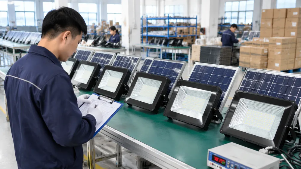
Sensor QC at factory level: JXSOL tests PIR function and lighting mode verification on every unit before shipment. Our integrated battery and LED module testing lab is in the same building as the assembly line, so every fixture goes through a sensor trigger test, a lumen output test, and a charge/discharge cycle test before it's packed. Many suppliers skip per-unit PIR testing and rely on batch sampling — test 10 units per 1,000, assume the rest are fine. Batch sampling misses sensors with calibration drift, damaged lenses, or incorrect wiring. The industry-standard defect rate for PIR modules from third-party suppliers is 2–3%. If you're ordering 500 units and the supplier uses batch sampling, expect 10–15 units with non-functional or hypersensitive sensors. You'll discover those during installation or shortly after, which means revisit costs and customer complaints. Per-unit testing costs us $0.90–1.10 per fixture in labor and test equipment time, but it reduces your field failure rate to under 0.3%.
Mounting vibration revisited: We mentioned this under placement, but it's worth repeating because it's a common root cause that buyers don't anticipate. If the fixture is mounted on a thin pole, a loose bracket, or a flexible surface (like vinyl siding or a wooden fence panel that flexes in wind), vibration will false-trigger the sensor. The pyroelectric element inside the PIR module is mounted on a flexible substrate for thermal isolation; mechanical vibration mimics the signal from moving thermal mass. The fix is rigid mounting on a solid surface: masonry, schedule 40 steel pipe, or a thick wood post (4x4 minimum). If your project requires mounting on a flexible surface, use a vibration-damping washer or specify a sensor module with mechanical isolation (available on OEM orders starting at 300 units). We've supplied units with damped sensor mounts for agricultural clients who install on thin-wall barn siding; it adds $1.80 per unit but eliminates the problem entirely.
Component quality determines whether your false alarm rate is 1–2 per month (acceptable) or 15–20 per month (unacceptable). Placement determines whether the sensor sees what you need it to see. Both matter. If you're comparing suppliers and one quote is 15% cheaper, ask what grade of PIR module they're using, whether sensitivity is adjustable, what the lens material is, and whether they test sensor function on every unit or just sample batches. Those answers will tell you whether the lower price is a real savings or a future liability.
Multi-Unit Layout Planning for Commercial and Residential Projects
Single-unit placement is straightforward — mount at the recommended height, angle downward 10°–15°, aim away from heat sources. Multi-unit layout requires coverage overlap planning so you don't create gaps where adjacent detection zones don't meet.
Coverage overlap calculation: If your sensor has a 10-meter detection range and a 120° horizontal angle, the effective arc width at 10 meters is roughly 17 meters (calculated as 2 × 10m × sin(60°)). For continuous perimeter coverage, space units 12–14 meters apart. That gives you 20–30% overlap, which compensates for sensor tolerance variation, mounting alignment errors, and approach angles that aren't perfectly perpendicular. Tighter spacing (8–10 meters) is overkill for most applications unless you're covering a high-security perimeter where detection redundancy matters more than unit cost.
Rectangular perimeter example: A 40m × 60m warehouse with 3.5-meter fence-top mounting. Place units at the four corners, each aiming along the adjacent wall. Add one unit at the midpoint of each long side (the 60-meter walls). Total: 6 units. Each unit covers roughly 12 meters of fence line with 20% overlap. Alternatively, if you center-mount one unit on each wall (4 units total), you'll have blind spots at the corners where approach paths are head-on to the sensors. The corner-mount layout uses two more units but eliminates the blind spots. For a distributor supplying 20 similar warehouses, that's 40 extra units per project, but it's also zero callbacks for "sensor didn't trigger at the corner."
Parking lot edge lighting: For a 100-meter parking lot perimeter fence, mount units every 12–15 meters at 3.5m height. Use corner-mount placement at the lot corners and space intermediate units along the long sides. For a rectangular lot, that's typically 8–10 units. Each unit triggers when a vehicle or pedestrian approaches within 10–12 meters, providing both security detection and task lighting for the perimeter walkway. The detection overlap ensures no gaps even if one unit's sensor drifts low on sensitivity over time.
Residential project bundle (5–10 units): A typical single-family residential security package includes 2 units on the garage (one per door), 1 unit per side gate, 1 unit on the rear fence or patio, and 1–2 units on the driveway approach. That's 6–8 units for complete perimeter coverage. Distributors can pre-configure this as a standard bundle with an installation guide that specifies mounting height (2.5m), tilt angle (10°–15° down), and approximate spacing. The bundle model reduces per-unit handling cost and gives your retail or contractor customers a ready-made package. We've supplied residential bundles for distributors in North America and Europe; the most common configuration is 6 units of the same model with mounting hardware included.
Terrain and obstacle considerations: Detection cones are line-of-sight. Large planters, parked vehicles, HVAC equipment, or grading changes block coverage. Before finalizing unit count, walk the site (or review the site plan) and map obstacles. If a vehicle is always parked in the same spot, that vehicle will block the detection zone behind it. Either increase unit count to cover the gap or accept the blind spot if it's low-priority. For sloped terrain, the detection range shortens uphill and extends downhill because the cone centerline intersects the ground at a different angle. A 10-meter sensor on a 10° upslope might deliver 8 meters of effective range uphill and 12 meters downhill. Account for this in spacing calculations.
For orders over 100 units where site layout determines final unit count — such as a contractor equipping a housing development with 50 homes (300 units) or a distributor supplying a commercial campus (150 units) — our engineering team can review the site plan and recommend unit count, fixture placement, and mounting height. We've done this for logistics centers, agricultural storage facilities, and multi-building residential projects. The review costs nothing and typically saves the buyer 10–15% on unit count by identifying where overlap can be reduced or where higher mounting can extend coverage per unit. The goal is to help you order the right quantity the first time, not to maximize unit sales.
Specification Parameters to Verify When Sourcing PIR Sensor Flood Lights
When you're comparing supplier quotes, the datasheet is where the differences show up. A cheaper unit might have a narrower detection angle, shorter range, fixed sensitivity, or lower-grade lens material. Here are the parameters that affect field performance and the questions to ask if the datasheet doesn't provide them.
Detection angle (horizontal and vertical): Rated as degrees, typically 90°, 120°, or 140° horizontal and 60° or 90° vertical. Wider horizontal angle means easier coverage per unit but more exposure to false alarm sources (passing traffic, distant movement). Narrower angle gives more selective triggering but requires tighter unit spacing for continuous coverage. Vertical angle determines how much coverage you have at close range directly below the fixture. A 90° vertical angle gives better near-field coverage than a 60° vertical angle. If the datasheet lists only one angle, assume it's horizontal and ask for the vertical spec.
Detection range: Rated distance in meters, typically 6m, 8m, 10m, or 12m for residential and light-commercial units. Verify whether the range spec is at the recommended mounting height or at a different test condition. Some suppliers inflate range by testing at ground level or using a high-contrast target in a controlled environment. The real-world range is 10–20% shorter than the datasheet claim, especially in hot climates or with low-thermal-contrast targets (someone wearing insulated clothing in cold weather). For project planning, use 80% of the stated range as your conservative estimate.
Sensitivity adjustment: Fixed, two-level switch, or continuous potentiometer. Fixed sensitivity means you can't tune for the environment; the installer gets what ships from the factory. Two-level (high/low) gives basic field adjustment for high-traffic vs. low-traffic areas. Continuous potentiometer gives full control but requires the installer to understand how sensitivity affects detection range and false alarm rate. For large projects where installation labor is expensive, factory-calibrated fixed sensitivity is often better than field-adjustable, because it eliminates the variability from 50 different installers making 50 different sensitivity decisions. We offer both: adjustable for distributors who want flexibility, factory-calibrated for contractors who want consistency.
Time delay setting: How long the light stays on after the last detected motion. Common values are 10s, 30s, 60s, or 120s. Shorter delay conserves battery in high-traffic areas (the light turns off quickly and re-triggers when the next person approaches). Longer delay reduces the number of charge/discharge cycles, which extends battery life. For perimeter security, 30–60 seconds is typical. For pathway lighting in high-traffic areas, 10–20 seconds is better. Some units offer adjustable delay; others ship fixed. If your application has varied traffic patterns (a warehouse entrance vs. a rear perimeter gate), adjustable delay is worth the extra $1.50 per unit.
IP rating for sensor lens and housing: IP65 minimum for outdoor solar applications. IP65 means dust-tight and protected against water jets from any direction. Lower ratings (IP44, IP54) mean moisture can enter the sensor housing during heavy rain, which degrades sensitivity and causes premature failure. We've seen units from low-cost suppliers fail within the first rainy season because the PIR module wasn't sealed properly. If the datasheet lists IP65 for the housing but doesn't specify the sensor module separately, ask. The housing might be IP65 but the sensor lens gasket might be IP54, which means water intrusion at the most vulnerable point.
Factory testing coverage: Per-unit testing or batch sampling. Per-unit testing means every fixture goes through a sensor trigger test before shipment. Batch sampling means the supplier tests a sample (10 units per 1,000, or similar) and assumes the rest are acceptable. Batch sampling is standard industry practice for consumer-grade products, but it's a problem for commercial projects where a 2–3% defect rate translates to field failures and callback costs. JXSOL uses per-unit testing because our target customers are distributors and contractors who deploy in volume and can't afford field failures. If the supplier doesn't state their testing method in the datasheet, ask. If they can't answer or say "we do random sampling," factor a 2–3% field defect rate into your cost estimate.
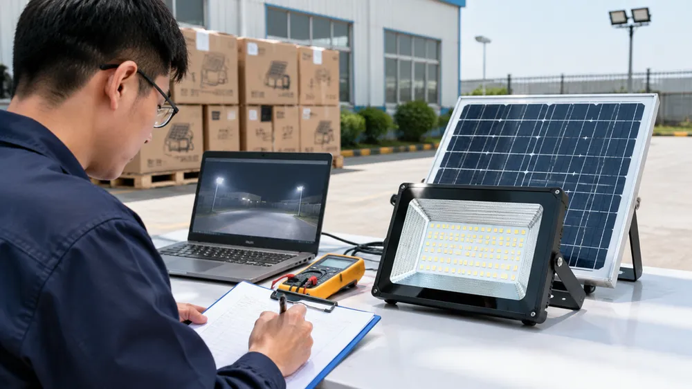
Procurement decision: For large projects (100+ units), request a sample batch of 10 units with the full datasheet. Test those units in your target environment for one week. Verify detection range at the planned mounting height, check for false alarms from wind-blown foliage or nearby traffic, and confirm that sensitivity adjustment (if present) actually changes behavior. One week of field testing costs you time but saves you from committing to 500 units that don't perform as claimed. We've had buyers order samples, test them against a competitor's samples, and switch suppliers based on real-world performance differences that didn't show up in the datasheet. That's exactly what the sample process is for.
How JXSOL's Sensor QC and OEM Configurability Reduce Deployment Risk
Most of what determines whether a solar motion flood light works reliably in the field comes down to two things: component quality and how well the sensor matches the deployment environment. JXSOL controls both.
We test PIR sensor function and lighting mode verification on every unit before shipment. The integrated battery and LED module testing lab is part of the same building as the assembly line, so every fixture goes through a three-stage test: sensor trigger response, lumen output at full charge, and battery charge/discharge cycle verification. The sensor test uses a calibrated motion simulator that crosses the detection field at a standardized speed and thermal contrast. If the sensor doesn't trigger within the spec window, the unit fails and goes to rework. This catches sensors with calibration drift, damaged Fresnel lenses, or wiring errors. Per-unit testing costs us $0.90–1.10 per fixture in labor and test equipment time, but it reduces field failure rates from the industry-standard 2–3% to under 0.3%. For a distributor deploying 500 units, that's the difference between 10–15 field failures and 1–2.
For OEM or project orders (MOQ 100 units), our engineering team can configure sensor sensitivity and detection angle to match the deployment environment. If you're supplying a retail perimeter where high foot traffic is normal and you want the sensor to ignore distant movement, we can factory-calibrate to lower sensitivity. If you're supplying a remote storage yard where any movement is significant and you want maximum detection range, we can calibrate to higher sensitivity. This configuration happens during assembly, not as a post-production adjustment, so the settings are consistent across the batch. Consistency matters when you're deploying 200 units and you want predictable behavior from all of them.
Factory-level adjustment is possible because we assemble PIR modules in-house. We don't drop-ship sensors from a third-party component supplier and hope they match the fixture spec. The sensor board, Fresnel lens, and housing are integrated on our SMT production line, and sensitivity calibration is part of the assembly process. That gives us control over the parameter that most affects field performance. For standing orders from distributors or contractors who deploy 500+ units annually, we can document the preferred sensitivity setting and apply it to every batch without requiring per-order specification. One distributor in Germany supplies solar flood lights to municipal parking lot projects; they specified a sensitivity setting that reduces false alarms from passing vehicles on adjacent streets. We've supplied that setting on every order for three years, and their callback rate for "too many false triggers" is under 1%.
The other advantage of in-house assembly is lead time for configuration changes. If a contractor tests a sample batch and wants the sensitivity adjusted, we can make that change and ship a revised sample within one week. Suppliers who source PIR modules from external vendors need 4–6 weeks to request a configuration change, receive new modules, and assemble test units. For project timelines where commissioning is scheduled and delays cost money, one week vs. six weeks matters.
This level of configurability isn't relevant for every buyer. If you're ordering 20 units for a single residential install, the standard factory setting works fine. But if you're a distributor supplying 50 contractors, or a contractor deploying 300 units across a commercial campus, or a project manager equipping a housing development with 500 units, factory-configured sensitivity and per-unit sensor QC reduce your deployment risk and your post-installation support costs. That's the buyer segment we built our production process around.