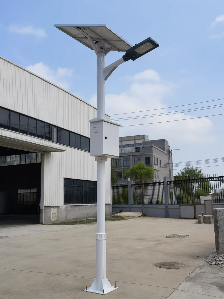
Why Connectivity Failures Happen at Handover (Not During Installation)
Most smart solar lighting system commissioning failures don't happen during physical installation. Mechanical mounting is verified first, electrical function gets tested next, and connectivity verification gets pushed to the end when contractors are already packing tools. That's when the problems surface: lights work perfectly, but the monitoring portal shows half the fixtures offline or network commands time out after three minutes.
Three failure modes account for 90% of handover connectivity issues. First, the network gateway wasn't provisioned correctly — it's powered on and shows green LEDs, but it never registered on the cellular network or completed the LoRa join sequence. Second, controller settings don't match the site plan — the dimming schedule uploaded during batch configuration references sensor IDs that were reassigned during installation. Third, PIR and photocell pairing was skipped entirely because the installer assumed "if the light turns on, it's commissioned."
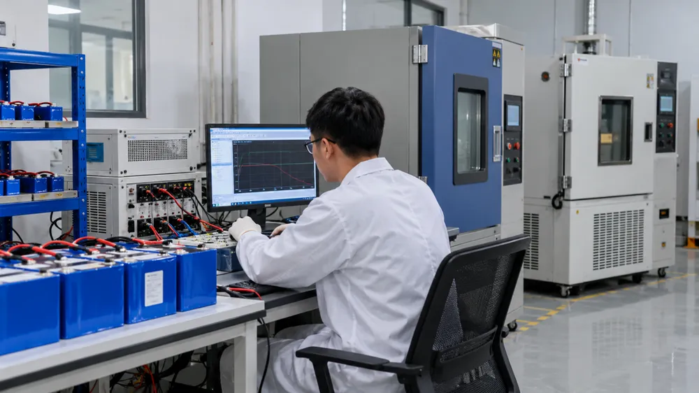
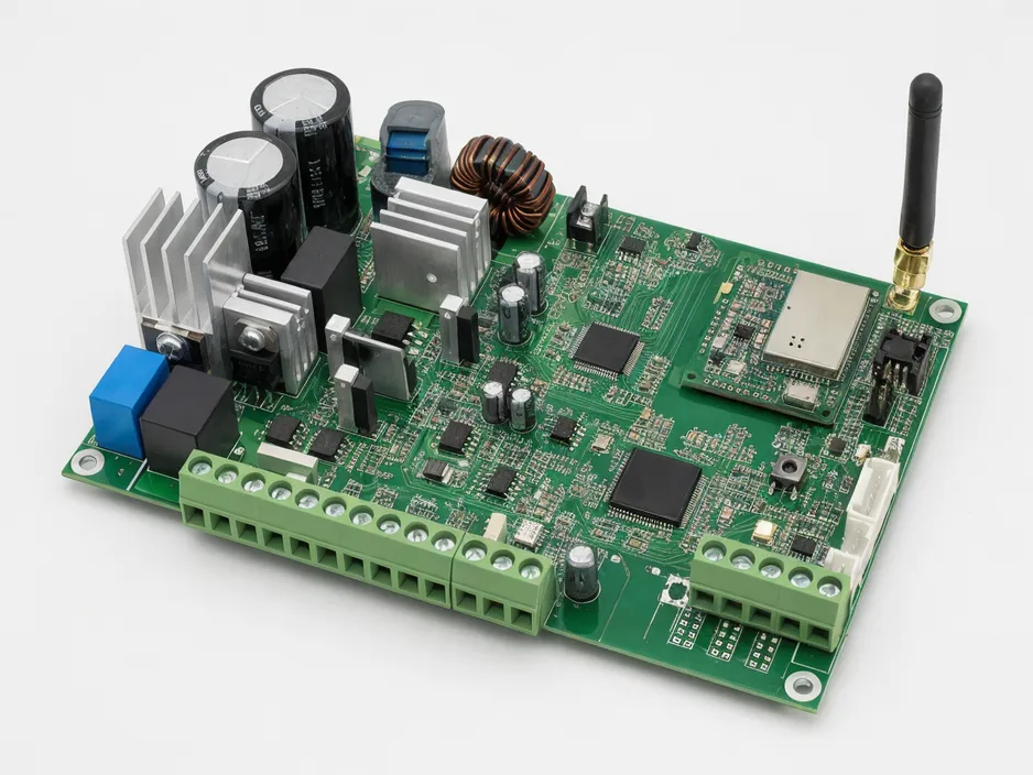
Here's the distinction that matters: factory testing verifies individual unit function under controlled conditions. We test every controller on a function bench, confirm the photocell triggers at the correct lux threshold, verify the PIR responds to motion at the specified detection angle, and log the firmware version and communication protocol handshake. Smart solar lighting system commissioning verifies system-level integration under actual site conditions — signal path obstructions, network congestion, controller-to-gateway pairing when 50 units are powering on simultaneously.
Handover is your last quality gate before the contractor leaves site. Connectivity failures discovered after handover cost 10 times more to fix because you're paying for a second site visit, troubleshooting without direct access to the installation crew who made the original configuration decisions, and explaining to the project owner why the remote monitoring they paid extra for doesn't work. Commissioning is verification, not troubleshooting. If you have the factory test baseline documented, the field check takes 30 minutes per fixture. If you skip the baseline and try to troubleshoot blind, you're guessing whether the root cause is a product defect, an installation error, or a site condition the original spec didn't account for.
Pre-Commissioning Checklist — Verify Before Site Activation
Fifteen minutes of desk work before you power on the first fixture prevents 90% of field rework. Start with the factory test reports. Every smart solar street light setup should include a controller function test log and sensor calibration certificate. Confirm you have them, verify the serial numbers match the units your installer actually received, and check that the firmware version on the test log matches what the site plan specifies. If the test log shows firmware v2.3 but your network gateway only supports v2.1 controllers, you're about to spend three hours on-site troubleshooting a compatibility issue the factory already documented.
Next, verify the site plan matches controller configuration. Open the batch configuration file your supplier provided (or the settings you uploaded to controllers during pre-staging) and cross-check three parameters: dimming schedule timing, sensor trigger logic, and communication protocol. If the site plan calls for 100% brightness from dusk to 10 PM, then 30% until dawn, but the configuration file shows a 50% setting, your first night of operation will generate fault reports. If the PIR is set to ramp to 100% and hold for five minutes, but the project owner expected a 30-second dwell time, you're reconfiguring on-site. If half the controllers are set to LoRa and the other half to NB-IoT because someone merged two batch files, your IoT solar lighting commissioning will fail before you finish pairing the first fixture.
Check that the network gateway is installed and has line-of-sight or a clear signal path to all fixture locations. For LoRa systems, that means no dense foliage or metal structures blocking the Fresnel zone between gateway and fixtures. For cellular (NB-IoT or LTE-M), confirm the gateway location has at least two bars of signal strength — one bar works in theory, but you'll see random dropouts under load. If you're using Zigbee mesh, verify the gateway is within 30 meters of at least three fixtures so the mesh can self-heal if one node drops.
Confirm your installer has completed mechanical and electrical installation per the site plan. That sounds obvious, but I've seen commissioning crews show up to find that two poles weren't installed yet, three fixtures were mounted backwards (solar panel facing north in the northern hemisphere), and one battery wasn't connected because the installer ran out of terminal connectors. Walk the site, visually confirm every fixture is mounted, and verify the solar panels are angled correctly before you start the electrical checks.
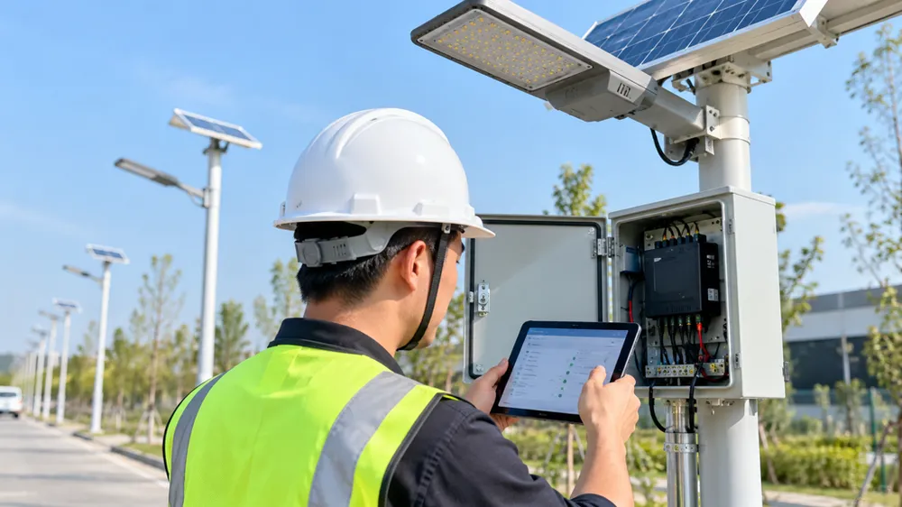
Finally, make sure your commissioning tools are ready: laptop with the controller configuration software installed and tested, RF signal strength meter (for LoRa) or a phone with a cellular signal app (for NB-IoT), and login credentials for the monitoring portal. Test the portal login before you leave the office. Half the "connectivity failures" I've diagnosed turned out to be contractors using the wrong portal URL or login credentials that hadn't been provisioned yet.
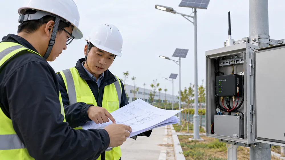
Step-by-Step Smart Solar Lighting System Commissioning Protocol
Phase 1: Physical and Electrical Verification (Per Fixture)
Start with the solar panel. Connect a multimeter to the panel output (before it reaches the controller) and measure open-circuit voltage under direct sunlight. Compare the reading to the voltage range on the factory spec sheet — typically 18-22V for a 12V system. If you're 3V low, the panel is defective or partially shaded. If you're measuring at 9 AM under cloud cover, come back at solar noon when the sun angle is optimal; testing under suboptimal conditions wastes time because you can't distinguish between a defective panel and insufficient irradiance.
Check battery charge state. Most smart solar lighting controllers have a status LED or LCD that displays battery voltage or state of charge percentage. If the fixture sat in a warehouse for three months before installation, you should see at least 50% charge if it was stored per factory guidelines (panels exposed to indirect light or charged once per month). If the battery is below 30%, it either self-discharged (which suggests a defective cell) or it wasn't maintained during storage. Don't proceed with commissioning until the battery is at least 50% — you need enough capacity to run the full test sequence without the battery protection circuit shutting down the controller mid-test.
Verify the LED driver output by triggering manual override mode. Most controllers have a test button or a jumper setting that forces the light to 100% output regardless of time or sensor state. Press the button (or connect the jumper), and confirm the fixture lights at full brightness. If it doesn't, check wiring polarity and insulation at all connectors. If polarity is correct but the light still doesn't activate, measure voltage at the LED driver input — you should see battery voltage minus 0.3-0.5V for the controller's internal drop. If driver input voltage is correct but there's no light output, the driver or LED module is defective (this happens in less than 0.5% of units, but it does happen).
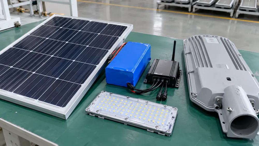
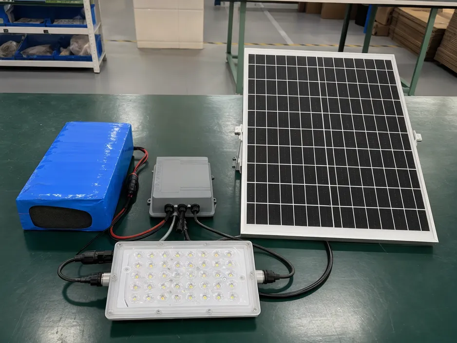
Confirm wiring polarity and connector insulation. Open the fixture housing (if it's a separate enclosure) or the pole base access panel (if wiring is routed internally) and visually inspect every connection: solar panel to controller, controller to battery, controller to LED driver, and controller to sensors (PIR and photocell). Polarity reversal won't always blow a fuse — some controllers have reverse-polarity protection — but it will prevent the system from charging or operating correctly. Check that all connectors are fully seated, no bare wire is exposed, and any IP67-rated cable glands are tightened to the manufacturer's torque spec (usually hand-tight plus one-quarter turn).
Phase 2: Controller Function Test (Per Fixture)
Power on the controller and watch the status LED sequence. Every controller manufacturer uses a different LED code, but the pattern is always documented in the manual. Typical sequence: red flashing for 3 seconds (initialization), green solid for 2 seconds (self-test passed), then green slow blink (normal operation, waiting for dusk). If you see red solid or red/green alternating, the controller detected a fault during self-test — usually a sensor not connected, battery voltage out of range, or firmware corruption. Cross-reference the LED code with the factory test log: if the same controller passed factory testing two months ago, the fault was introduced during installation or storage.
Trigger the photocell manually by covering the sensor with opaque tape or a cloth. The fixture should activate within 5 seconds and follow the programmed dimming schedule. If it's 2 PM and your schedule says "activate at 100% from dusk to 10 PM, then dim to 30% until dawn," the light should turn on at whatever brightness corresponds to the time-of-day setting (most controllers calculate time since dusk internally, so you might see 30% even though it's daytime). If the light doesn't activate, either the photocell threshold is set incorrectly (too low, so it thinks it's still daylight even when covered), the photocell isn't connected, or the controller's dusk detection logic is disabled. Don't assume the factory setting is correct — I've seen batch configuration errors where 50 controllers were accidentally set to "manual mode only."
Trigger the PIR manually by walking in front of the sensor at the detection range specified in the datasheet (typically 5-8 meters for a 120-degree PIR). The light should ramp from its current dim level to 100% and hold for the programmed dwell time (usually 30 seconds to 5 minutes, depending on application). If it doesn't respond, confirm the PIR is powered (some controllers have a separate enable setting for motion sensing), check the detection angle (PIR must be aimed at the area you're testing, not at the sky), and verify the sensitivity isn't set to minimum (which shortens detection range to 2-3 meters). If the light ramps to 100% but drops back immediately, the dwell time setting is probably 0 seconds — a common configuration error during batch programming.
If any function test fails, pull the factory controller test log and compare. The log should show the date the controller was tested, the firmware version, and pass/fail results for photocell trigger (with the lux threshold used), PIR trigger (with the distance and angle tested), and dimming curve accuracy. If factory testing shows a pass but field testing shows a fail, the root cause is installation (wrong setting uploaded, sensor not connected, or physical damage during shipping). If factory testing shows a fail or the test log is missing, you have a quality control gap to escalate with your supplier. (We test every controller before it leaves the factory, so if you're sourcing from JXSOL and the test log is missing, contact the technical team — that's not normal.)
Phase 3: Network Pairing and Connectivity Verification (System-Level)
Power on the gateway first, not the fixtures. This is the single most common mistake in IoT solar lighting commissioning. If you power on 20 fixtures before the gateway is confirmed online, those controllers will attempt to join the network, time out after 60-90 seconds, and enter a retry backoff mode that delays the next join attempt by 10-15 minutes. You'll spend an hour waiting for timeouts and resets. Instead, power on the gateway, wait for the status LED to show network registration (solid green for LoRa, solid blue for cellular), and confirm it appears in the monitoring portal as "online" before you touch the first fixture.
For LoRa gateways, network registration means the gateway completed a join-accept handshake with the LoRaWAN network server. Check the gateway's web interface or LCD (if it has one) for the "joined" or "connected" status. For cellular gateways (NB-IoT or LTE-M), registration means the gateway obtained an IP address from the carrier and established a data session with the monitoring platform's cloud server. You should see the gateway's IMEI or serial number appear in the portal's device list within 2-5 minutes of powering on. If it doesn't appear, troubleshoot the gateway first — check SIM card installation (for cellular), confirm the antenna is connected, verify the gateway is in range of the network (for LoRa, check the nearest public gateway location; for cellular, confirm signal strength is at least -110 dBm or two bars).
Activate each fixture in pairing mode. Most smart solar lighting controllers enter pairing mode automatically on first power-up, but if the fixture was powered on during installation testing and then powered off, you'll need to manually trigger pairing. The procedure varies by manufacturer, but the most common method is to press and hold the controller's function button for 10 seconds, release, and wait for the LED to flash rapidly (indicating pairing mode active). Some controllers use a jumper instead of a button — connect jumper pins 1 and 2, power on, wait 10 seconds, remove jumper. Check the controller manual for the exact sequence.
Confirm the gateway receives each fixture's ID and reports online status in the monitoring portal. After you activate pairing mode, the fixture should transmit a join request within 30 seconds. The gateway receives the request, forwards it to the network server, and the server adds the fixture to your project's device list in the portal. Refresh the portal page — you should see a new device appear with the fixture's unique ID (usually the controller serial number or a LoRa DevEUI). Initial status might show "joining" for 30-60 seconds, then switch to "online." If the fixture doesn't appear after 90 seconds, either the join request didn't reach the gateway (signal strength too weak, wrong frequency band, or controller isn't in pairing mode) or the gateway isn't forwarding join requests to the server (gateway offline, wrong network credentials, or firmware bug).
Test remote command functionality before moving to the next fixture. Select the newly paired fixture in the portal and send a dim or brighten command (most portals have a "test" or "control" tab where you can manually set brightness to a specific percentage). The fixture should respond within 30 seconds — for LoRa, typical latency is 10-20 seconds because of duty-cycle limits; for cellular, latency is 5-10 seconds. If the fixture doesn't respond, check two things: first, confirm the command was actually sent (portal should show "command pending" or "sent" status); second, verify the controller is listening for downlink commands (some controllers only check for commands once per minute to save battery, so you might need to wait up to 60 seconds for a response). If remote commands never work, the controller's downlink reception is disabled or the gateway's downlink path isn't configured (common issue with LoRa gateways that have separate uplink and downlink configuration).
Walk the signal path for edge fixtures and measure signal strength. Once all fixtures are paired, identify the fixtures farthest from the gateway and check their signal quality. For LoRa, use the portal's signal strength indicator (usually labeled RSSI, measured in dBm — higher is better, less negative). If RSSI is worse than -120 dBm, the link is marginal and will drop under interference or when foliage grows in the spring. For cellular, check the controller's signal strength reading (if it has an LCD) or the gateway's signal report in the portal. If signal is below two bars (-110 dBm for LTE-M, -115 dBm for NB-IoT), plan for a repeater or gateway relocation before handover — you don't want to accept a system that will fail in six months when the trees fill in.

Phase 4: System Integration and Schedule Verification (Before Handover)
Confirm all fixtures report to the portal with correct location tags. Open the portal's map view or device list and verify every fixture appears with the location label that matches your site plan (if the project uses GPS coordinates, confirm lat/long accuracy is within 10 meters — some controllers report GPS from the last known position, which can be wrong if the unit was tested at the factory and then shipped without clearing the GPS cache). Incorrect location tags turn into a maintenance nightmare six months later when the project owner reports "light 37 is offline" and no one knows which physical fixture that refers to.
Verify the dimming schedule uploaded to all controllers matches the site plan. Select five fixtures at random (include at least one edge fixture and one fixture near the gateway) and check their configuration in the portal. Compare the programmed schedule to the site plan: activation time relative to dusk, dim percentage and timing for each period, motion-sensing enable/disable state, and dawn deactivation logic. If you find a mismatch, check whether it's a one-off error (wrong setting on one controller) or a batch error (wrong configuration file uploaded to all controllers). Batch errors are faster to fix — re-upload the correct schedule to all fixtures and verify they accept the new settings. One-off errors mean you need to manually reconfigure each affected unit.
Test fault alert functionality by simulating a common failure mode. The easiest test is to manually disconnect one fixture's solar panel while the system is running (do this during daytime so the battery isn't actively charging — you're testing fault detection, not creating an actual battery drain scenario). The controller should detect the loss of solar input within one charge cycle (typically 15 minutes to 1 hour, depending on how often the controller samples panel voltage) and report a "solar panel fault" or "no charge" alert to the portal. If the alert appears, fault monitoring is working. If no alert appears after two hours, either fault reporting is disabled in the controller configuration or the monitoring platform isn't configured to accept fault messages from this device type. Reconnect the panel and verify the fault clears within the next reporting cycle.
Run a 24-hour monitoring cycle before final handover. This is non-negotiable for any project over 50 fixtures or any site where you won't have easy access for post-handover adjustments. Power on the system at dawn, let it run through one full day (solar charging during daytime, activation at dusk, dimming and motion response overnight, deactivation at dawn), and confirm every fixture reports expected data: solar panel voltage peaked during midday, battery charged to 90-100% by dusk, light activated within 5 minutes of the programmed dusk time, motion events (if applicable) were logged, and battery voltage at dawn was still above the low-voltage cutoff threshold. Any fixture that doesn't complete the full cycle is flagged for troubleshooting before handover. Common issues found during 24-hour testing: one controller has the wrong time zone setting so it activates two hours early, one battery has a weak cell and drops to cutoff voltage by 3 AM, one PIR sensor is aimed at a tree branch and logs 200 false motion triggers per night (draining the battery faster than the panel can recharge).
Common Commissioning Mistakes and How to Avoid Them
Skipping factory test report verification
If you don't verify the factory test baseline before commissioning, you can't distinguish between a product defect and an installation error. I've watched contractors spend four hours troubleshooting a photocell that "doesn't work," only to discover the controller was shipped with photocell detection disabled because the original order specified manual-only operation. The factory test log would have shown that setting immediately.
Correct procedure: Request the controller function test log and sensor calibration certificate from your supplier before the equipment ships. When the units arrive on-site, verify serial numbers on the physical controllers match the serial numbers on the test logs. Check that firmware version, sensor thresholds, and communication protocol settings match what your site plan specifies. If there's a mismatch, resolve it before installation begins — not during commissioning when the contractor is already on-site and the clock is running.
Pairing fixtures before gateway is confirmed online
When you power on fixtures before the gateway completes network registration, every controller attempts a join request, waits 60-90 seconds for a response that never comes, then enters a retry backoff mode. Depending on the controller firmware, the next retry might happen in 10 minutes, 30 minutes, or not until the next power cycle. You'll waste an hour power-cycling fixtures and waiting for timeouts, and you still won't have reliable pairing because controllers are retrying at random intervals and colliding with each other.
Correct procedure: Power on the gateway, wait for the status LED to show network registration (solid green for LoRa, solid blue for cellular), open the monitoring portal and confirm the gateway appears in the online device list, then and only then start powering on fixtures one at a time. If you're commissioning more than 20 fixtures, power them on in groups of five and wait for each group to complete pairing before starting the next group — this reduces join request collisions and makes it easier to identify which specific fixture failed to pair.
Testing connectivity indoors or without line-of-sight verification
I've seen contractors test IoT solar lighting commissioning in a warehouse, confirm all fixtures pair successfully, then install them on-site and discover that half the fixtures can't maintain a connection because the signal path is blocked by a metal building. Indoor testing gives you a false pass because the gateway and fixtures are 10 meters apart with no obstructions. Site conditions are completely different: fixtures are 50-200 meters from the gateway, trees and buildings create Fresnel zone blockages, and RF noise from nearby industrial equipment raises the noise floor.
Correct procedure: If you must pre-test fixtures before installation (for example, to reduce on-site commissioning time), test them in their final installed position or at least at the same height and distance from the gateway. For smart solar street light setup, that means mounting at least three test fixtures on temporary poles at representative distances (near, middle, and far from the gateway), running the full pairing and connectivity test, and measuring signal strength at each location. If edge fixtures show RSSI worse than -115 dBm (LoRa) or signal strength below two bars (cellular), plan for a repeater or gateway relocation before you install the other 47 fixtures.
Not documenting controller configuration settings during commissioning
Six months after handover, the project owner calls and says "fixture 23 is dimming at the wrong time, what settings did we use?" If you didn't document the controller ID, firmware version, and programmed schedule during commissioning, you're troubleshooting blind. You can't confirm whether the setting changed (which suggests someone accessed the controller or the settings were overwritten during a firmware update) or whether the setting was wrong from day one and no one noticed until now. Without a configuration log, the factory can't provide remote support because we don't know what settings you actually deployed.
Correct procedure: Create a commissioning log spreadsheet before you start. For each fixture, record the controller serial number, firmware version, photocell and PIR threshold settings, dimming schedule, network protocol and join timestamp, and signal strength at first pairing. Take a screenshot of the portal's device configuration page for at least 10% of the fixtures (more if it's a large project). Store the log and screenshots with the project handover documentation — the project owner will thank you when they need to troubleshoot a year later, and your factory support team can diagnose issues in 10 minutes instead of three hours.
Handover before 24-hour monitoring cycle completes
Completing mechanical installation, running a 30-minute connectivity test, and calling it done is the fastest way to generate post-handover failure reports. Intermittent issues don't show up in short tests: a battery with one weak cell passes the initial charge state check but drops to cutoff voltage at 2 AM under load. A solar panel with a hairline crack in one cell shows correct voltage under bright midday sun but undercharges on cloudy days. A PIR sensor aimed slightly wrong logs 50 motion events per night when tree branches sway, draining the battery 30% faster than your charging calculation assumed.
Correct procedure: After completing Phase 3 network pairing, let the system run through one complete 24-hour cycle before scheduling the handover meeting. Monitor the portal during that period and flag any fixture that reports abnormal data: battery didn't reach 90% charge by dusk, light didn't activate within 10 minutes of programmed dusk time, motion event count is 10x higher than other fixtures, battery voltage at dawn is below 60% (suggesting insufficient solar charging or excessive load). Troubleshoot flagged fixtures during the monitoring period, not after the contractor leaves site. For projects over 200 fixtures, run a 48-hour cycle — the second night catches intermittent issues that only happen after the battery goes through one full discharge/charge cycle.
How JXSOL Factory QC Supports Field Commissioning
Every smart solar lighting controller we ship goes through a function bench test before it leaves the factory. The test sequence verifies photocell trigger response (we apply a calibrated light source, vary the intensity from 100 lux down to the trigger threshold, and confirm the controller activates within the specified lux range — typically 8-12 lux for dusk detection), PIR motion response (we trigger the sensor at the rated detection distance and angle, confirm the controller ramps to 100% brightness within 2 seconds, and verify dwell time accuracy), dimming curve accuracy (we program a test schedule, force the controller through each dimming step, and measure actual LED output with a calibrated lux meter — it must match the programmed percentage within ±5%), and communication protocol handshake (we pair the controller with a test gateway using the same protocol your order specifies, send a remote command, and confirm the controller executes it within 30 seconds).
Sensor calibration happens on a separate test bench before the controller test. PIR detection angle and range are verified against the datasheet using a motion target at known distances — 5 meters, 8 meters, and 10 meters for a standard 120-degree PIR. We confirm the sensor triggers reliably at the rated range and doesn't trigger outside the rated angle (false triggers caused by motion outside the coverage area kill battery life). Photocell threshold is set to the IEC 62176 standard for dusk detection: 10 lux with a tolerance of ±2 lux. We verify threshold accuracy with a calibrated light box, adjust the photocell's sensitivity trimmer if needed, and lock it with tamper-resistant adhesive.
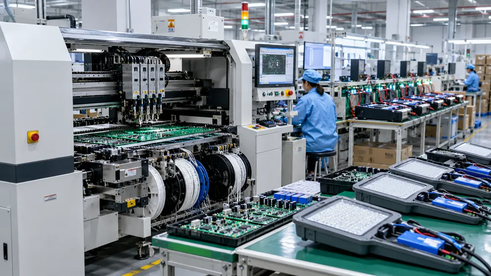
Before we ship any IoT solar lighting order, we run a pre-shipment pairing test using a gateway prototype configured with the same communication protocol, frequency band, and network credentials your site will use. We pair 10 sample controllers (randomly selected from your production batch), confirm they join the network within 60 seconds, send remote commands to each controller, and verify response time is under 30 seconds. This catches protocol compatibility issues before the equipment leaves the factory — for example, if your order specifies LoRa AS923 (Asia frequency band) but the controllers were accidentally flashed with EU868 firmware, the pairing test will fail and we'll re-flash the correct firmware before shipment.
Every controller ships with a factory test log: a printed or digital document that lists the controller serial number, firmware version, test date and pass timestamp, photocell threshold setting, PIR detection range and angle, dimming curve test results, and communication protocol handshake confirmation. For projects over 500 units, we provide a batch test summary that shows pass rate, any units that failed initial testing (and whether they were retested and passed or scrapped), and firmware version distribution if your order includes multiple production runs.
Why this matters for smart solar lighting system commissioning: when you run the field commissioning protocol, you're verifying that the controller's field behavior matches its documented factory baseline. If a controller passes the factory photocell test (log shows trigger at 10 lux, test date two months ago) but fails your field test (doesn't activate when you cover the photocell), the root cause is installation-related (wrong setting uploaded during batch configuration, photocell physically damaged during shipping, or photocell connector not fully seated). If a controller fails both factory and field testing, or the factory test log is missing, you have a quality control gap to escalate with your supplier. Knowing the baseline cuts troubleshooting time by 70% because you're not guessing whether the product was defective from the start or something went wrong during installation.
Factory test logs are available on request for any JXSOL project. For orders over 500 units, we include them automatically in the shipment documentation. For smaller orders, request them when you place the order or during production — they're generated during final QC, so as long as you ask before the shipment leaves the warehouse, we can include them. The logs are also useful for contractor handover documentation: when you hand over the project to the owner, include the factory test logs to prove that every controller was verified functional before installation, which protects you from liability if a failure turns out to be a product defect rather than an installation error.
Commissioning Documentation and Handover Requirements
Document six data points for every fixture during commissioning: fixture physical location and serial number (reference the site plan's pole or fixture ID), controller serial number and firmware version (from the controller's label or the factory test log), network signal strength at first pairing (RSSI in dBm for LoRa, signal bars or dBm for cellular), dimming schedule and sensor settings currently programmed (screenshot from the portal's device configuration page), photocell and PIR trigger test results (pass/fail and any notes about threshold adjustments made on-site), and 24-hour monitoring log screenshot showing one complete day/night cycle with battery charge/discharge data. Store this data in a spreadsheet or commissioning checklist form — it takes 3-5 minutes per fixture during the actual commissioning work, but it's worth it.
Why documentation matters: it supports warranty claims (if a controller fails three months after handover and the factory asks whether the controller was tested before installation, your commissioning log proves it was), it enables remote troubleshooting (when a fixture reports a fault, you can compare current behavior to baseline behavior documented during commissioning and identify what changed), and it's required by some project owners for final payment release (government and institutional projects often require commissioning logs as part of the acceptance documentation). I've seen contractors lose final payment because they couldn't produce commissioning records proving that connectivity testing was actually performed.
Your handover package for the project owner should include five documents: completed commissioning checklist with pass/fail status for every fixture, factory test reports for controllers and sensors (if your supplier provided them — JXSOL includes these for orders over 500 units), network topology diagram showing gateway location and approximate signal coverage zones, monitoring portal login credentials and a quick-start guide for basic portal functions (how to view device status, how to send remote commands, how to interpret fault alerts), and installer contact information with a defined availability window for post-handover support (typically 30-90 days depending on project terms). Organize these documents in a binder or a shared drive folder, and hand them over during the final walkthrough meeting, not via email two weeks later when the project owner has already forgotten half the system details.
Schedule a handover meeting, don't just email a login and call it done. Walk the project owner through the monitoring portal: show them how to view the device list and map, demonstrate sending a remote dim command to one fixture so they understand the latency and confirmation process, explain how to interpret the three most common fault alerts (solar panel fault, battery low voltage, communication timeout), and confirm which faults require immediate action versus which faults can wait for scheduled maintenance. Give them the installer's contact information and clarify the support window: "For the next 60 days, if you see a fault alert or a fixture isn't responding to remote commands, call this number and we'll send someone to site within 48 hours. After 60 days, contact your maintenance contractor." Setting expectations during handover prevents angry calls six months later when the owner discovers that post-warranty support costs extra.
Professional handover documentation reduces post-project support calls by 70% because the project owner has the information they need to distinguish between normal system behavior and actual faults, and they know who to call for each type of issue. It also protects you legally: if a dispute arises about whether commissioning was performed correctly, your documentation proves exactly what was tested, when, and what the results were. For contractors, good documentation is the difference between getting paid on time and spending three months negotiating with a project owner who claims "the system was never properly commissioned."
When to Escalate — Factory Support for Commissioning Failures
Try to resolve commissioning issues on-site first because 80% of failures are network setup errors or configuration mismatches, not product defects. If a fixture won't pair, check gateway online status, verify the controller is in pairing mode (LED should flash rapidly), confirm signal strength is adequate (RSSI better than -120 dBm for LoRa, two bars minimum for cellular), and verify the controller's frequency band matches the gateway (a common issue when mixing equipment from different regional shipments — AS923 controllers won't pair with an EU868 gateway). If a controller fails a function test, cross-check the factory test log to see whether that function passed at the factory, verify you're triggering the test correctly (photocell must be fully covered to block all light, PIR test requires motion within the rated detection range), and confirm the setting wasn't accidentally changed during batch configuration. Work through the protocol steps in Section 3 systematically — most field issues are caught by repeating the procedure with closer attention to detail.
Escalate to factory support when you've confirmed the issue isn't installation-related: controller fails a function test (photocell, PIR, or dimming) that the factory test log shows passed two months ago, firmware version on the physical controller doesn't match the version listed on the factory test log or the version your site plan specified, repeated pairing failures across multiple controllers from the same production batch (suggests a protocol compatibility issue or a batch firmware error), or sensor calibration drift outside the tolerance range specified in the datasheet (for example, photocell triggers at 20 lux instead of the rated 10 lux, or PIR detection range is 3 meters instead of the rated 8 meters). These symptoms indicate either a product defect, a firmware bug, or a batch configuration error that happened at the factory — all of which require factory-level diagnosis and correction.
When you escalate, provide five pieces of information: controller serial number (from the label on the controller housing), factory test log (if available — include the test date and pass/fail status for the function that's now failing), photo or video of the controller's status LED behavior (helps diagnose fault codes and startup sequences), network signal strength reading from the portal or your RF meter (RSSI in dBm for LoRa, signal bars or dBm for cellular), and a description of which commissioning step failed and what you observed (for example, "Phase 2, photocell trigger test — covered sensor with opaque cloth, waited 30 seconds, no light activation, controller LED remains green slow blink"). The more specific you are, the faster we can diagnose the root cause.
JXSOL's technical support protocol for solar lighting connectivity troubleshooting: email the commissioning failure data to our technical team at the support address provided with your order documentation ([email protected] can route it if you don't have the direct support contact). For projects over 200 units, we respond within 24 hours with either a diagnosis and fix procedure or a request for additional diagnostic data. If the failure requires remote diagnostics, we'll ask you to add our support team's login to your monitoring portal so we can view the device's reported data, send test commands, and check firmware version and configuration remotely. For product defects confirmed by remote diagnosis, we'll either walk you through a field fix (firmware re-flash, sensor recalibration, or configuration adjustment) or authorize a replacement unit and provide the replacement controller's serial number and factory test log before it ships.
Factory support is for product defects, firmware bugs, and system integration issues — not for installer training or configuration questions that should have been resolved before commissioning started. If you need help understanding how to set a dimming schedule or how to pair a controller, those questions should go to your supplier's sales or technical team during the pre-installation phase, not during on-site commissioning when you're troubleshooting an actual failure. Clear escalation criteria keep the commissioning schedule on track and ensure factory support resources go to issues that actually need factory-level diagnosis, which means faster turnaround time for everyone.