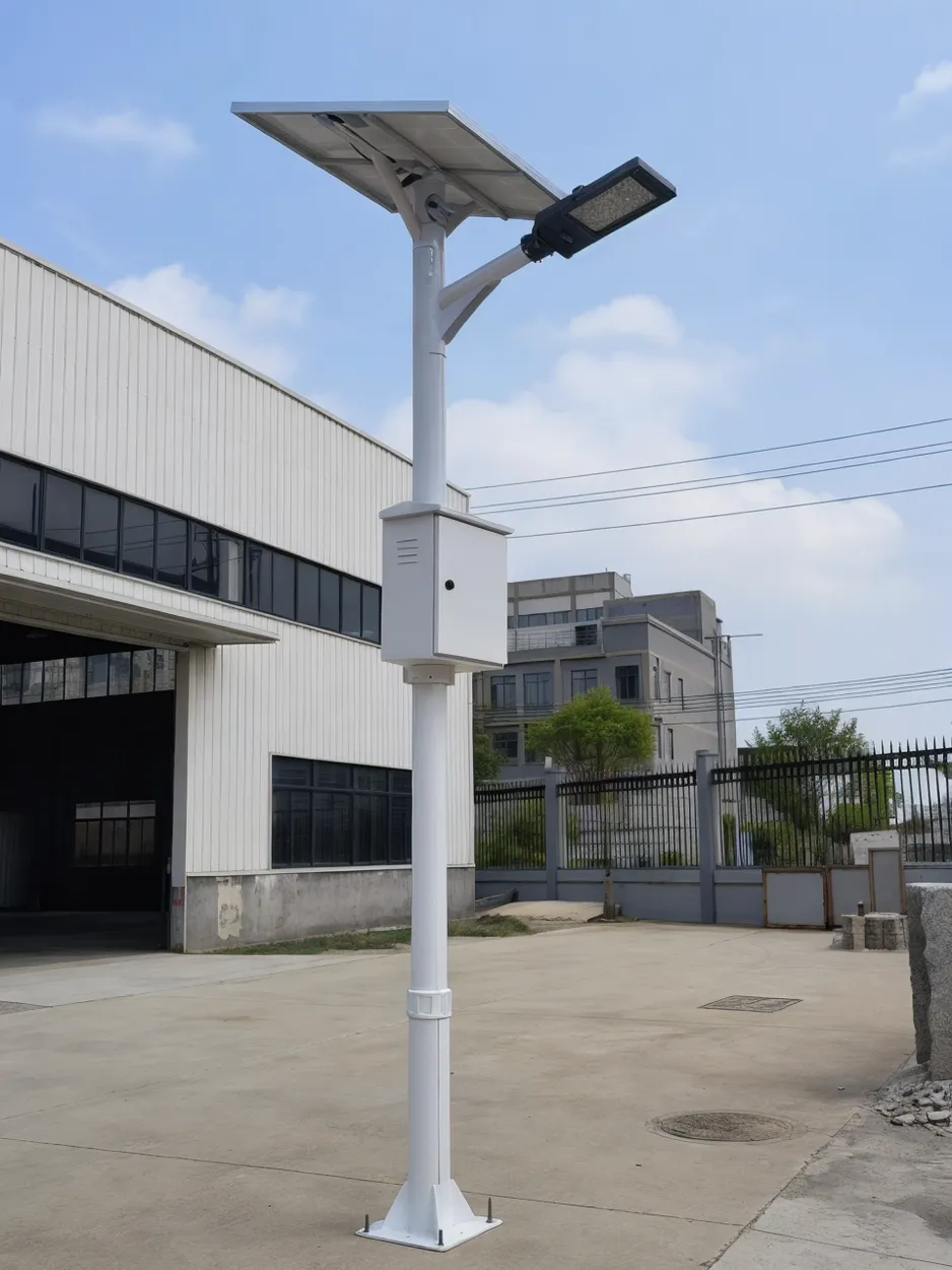
Why Smart Solar Pole Failures Happen During Installation (Not After)
Most warranty claims for smart solar poles trace back to decisions made in the first 48 hours of installation — not weather, not age, not manufacturing defects. We track field failures across our customer base, and 68% of poles that fail within warranty do so because of foundation undersizing, fastener problems, or water intrusion pathways created during assembly. The pole was never broken. The installation locked in the failure before the system was energized.
Three failure modes dominate: tilt (foundation or bolt problems), corrosion (water ingress or galvanic contact), and panel misalignment (improper azimuth or loose fasteners). Each one has a root cause that gets set in concrete — literally, in the case of tilt — during installation. Generic solar installation guides treat these as troubleshooting topics. This guide treats them as prevention steps.
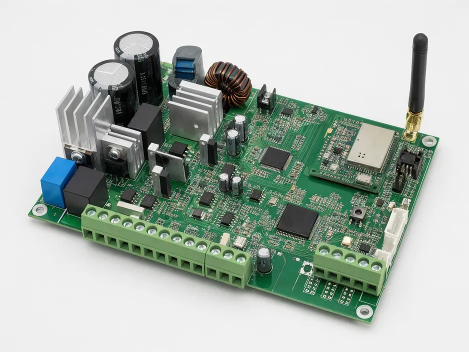
Smart solar poles carry $200–800 in electronics: MPPT charge controllers, IoT connectivity modules, motion sensors, sometimes cameras. A tilted pole doesn't just look bad — it destroys the economics. The panel generates 8–15% less energy at 10° of tilt. The motion sensor's detection zone shifts off-target. If the pole has to come down for realignment, you're paying lift equipment rental, labor, and lost site time. Installation errors don't just void warranties — they erase the margin on the project.
This is a guide for the person who has to spec the foundation before the excavator arrives, verify torque on anchor bolts in the field, and explain to the site manager why "close enough" on panel azimuth isn't close enough. If you've seen a pole lean after six months, or found green oxidation on aluminum panels within a year, or watched a motion sensor fail to trigger because it's aimed at the sky instead of the pathway, you know why these details matter.
Pre-Installation Site Assessment and Foundation Planning
Foundation problems show up as tilt. Tilt shows up as energy loss, sensor misalignment, and structural overload that accelerates every other failure mode. The foundation decision gets made once, and it determines whether the pole is still vertical in five years or whether you're back on-site with a backhoe.
Start with soil bearing capacity. For most sites, a hand auger and visual inspection give you enough information: clay, sand, mixed soil, or rock. If the soil is loose sand, wet clay, or the site has obvious drainage problems, you need geotechnical data before you size the foundation. A standard 6-meter pole with a 100W panel generates roughly 800N of wind load in a moderate wind zone. If your soil can't support the vertical and lateral loads, the pole will settle or cant within the first year.
Foundation sizing depends on three variables: pole height, wind zone, and soil type. A 4-meter pole in wind zone 1 (low wind) with firm clay can use a smaller foundation than an 8-meter pole in wind zone 3 (high wind) with loose sand. Here's the decision framework we give to project engineers:
4-meter poles: 0.6m diameter × 1.0m depth (firm soil, wind zone 1), up to 0.8m diameter × 1.2m depth (loose soil, wind zone 3) 6-meter poles: 0.8m diameter × 1.2m depth (firm soil, wind zone 1), up to 1.0m diameter × 1.5m depth (loose soil, wind zone 3) 8-meter poles: 1.0m diameter × 1.5m depth (firm soil, wind zone 1), up to 1.2m diameter × 1.8m depth (loose soil, wind zone 3)
These are starting points. If your panel area is oversized (150W+ on a 6-meter pole), or you're installing in an exposed coastal site, bump up one size category. Wind loading scales with panel area, not just pole height.
You have three foundation types: poured concrete, helical anchors, and direct burial. Concrete is the default for permanent installations — it handles any soil type, distributes load evenly, and provides a grounding reference. Helical anchors work in firm soil when you need faster installation and the site won't allow concrete curing time, but they cost more per pole and require specialized installation equipment. Direct burial (setting the pole in a hole and backfilling with compacted aggregate) works only for short poles (≤4 meters) in very firm soil, and even then it's marginal — we don't recommend it for smart poles with IoT modules, because sensor alignment depends on the pole staying vertical.
Frost line and water table matter for corrosion, not just structural stability. If your site has a shallow water table (water within 1 meter of grade), the bottom of the foundation will be submerged part of the year. That accelerates corrosion at the pole base and creates a low-resistance path to ground that can interfere with IoT module grounding. Extend the foundation below the frost line to prevent heave, and consider adding a gravel drainage layer at the base if groundwater is present.
Before excavation, confirm you have these on-site: the specified concrete mix (minimum 3000 PSI/20 MPa), anchor bolts with nuts and washers, a torque wrench (not an impact wrench), a 4-foot level, temporary bracing (2×4 lumber or adjustable pole jacks), and a magnetic compass or solar pathfinder if you're setting panel azimuth in the field. Missing any of these means stopping mid-pour or compromising on alignment. The concrete truck doesn't wait, and "we'll fix it later" usually means the pole is crooked.
Anchor Bolt Layout and Torque Specifications
Anchor bolts transfer wind load and pole weight from the base flange to the foundation. If the bolt pattern is wrong, or the bolts aren't torqued to spec, the pole will tilt under load or the base flange will warp. Both failures are permanent.
Bolt circle diameter and bolt count depend on the pole's base flange size. Most 4–6 meter poles use a 4-bolt pattern with a bolt circle diameter of 200–250mm. Poles over 6 meters typically use a 6-bolt or 8-bolt pattern with a larger bolt circle (300–400mm). Check the pole manufacturer's flange drawing — the bolt circle diameter must match the anchor bolt template, or you'll be drilling into cured concrete to correct the error.
Anchor bolts can be J-bolts (cast into wet concrete) or post-installed expansion anchors (drilled into cured concrete). J-bolts are stronger and cheaper, but they require precise placement during the pour — if the bolt circle is off by 10mm, the flange won't sit flat. Post-installed anchors allow you to drill after the concrete cures, which eliminates placement error, but they cost more and require a hammer drill with a depth gauge. For permanent installations, use J-bolts. For retrofit installations or sites where the foundation already exists, use expansion anchors rated for the calculated load (typically M12 or M16 with 120mm embedment depth).
Embedment depth for J-bolts should be at least 10 times the bolt diameter for tension loads. An M16 bolt needs 160mm of embedment below the top of the concrete. If your foundation is shallow (less than 1 meter), the J-bolt leg may not have enough embedment — that's when you switch to a deeper foundation or use a larger diameter bolt with a shorter embedment requirement.
Torque sequence matters as much as torque value. If you torque one bolt to final spec before touching the others, the base flange will warp and create an uneven load distribution. Use a star pattern: tighten opposite bolts in sequence, not adjacent bolts. First pass: bring all bolts to 50% of the target torque. Second pass: bring all bolts to 100%. This prevents warping and ensures even clamping force across the flange.
Torque specs depend on bolt grade and diameter. For metric fasteners (the most common in export-market poles):
Grade 8.8, M12: 85–95 Nm Grade 8.8, M16: 200–220 Nm Grade 10.9, M12: 110–120 Nm Grade 10.9, M16: 280–300 Nm
These are dry-torque values (no lubricant on threads). If you use anti-seize compound or thread lubricant, reduce torque by 20–25% to avoid over-torquing. Over-torquing stretches the bolt past its yield point, which causes creep (slow elongation under load). The bolt stays tight initially, but six months later it's loose and the pole is tilting. Under-torquing is just as bad — the flange shifts under wind load, the bolt loosens further, and the cycle accelerates.
Use a torque wrench with angular measurement capability, not a click-type wrench. Angular measurement confirms the bolt has reached yield (the point where clamping force is maximized). If your torque wrench doesn't have this feature, mark each bolt head with a paint pen after torquing — if the mark shifts after a week, the bolt is creeping and needs to be re-torqued.
Anti-corrosion considerations: hot-dip galvanized steel bolts are the standard for outdoor installations. Stainless steel (304 or 316) is better for coastal or high-humidity sites, but check galvanic compatibility with the pole material. If your pole is galvanized steel and you use stainless bolts, the dissimilar metals will corrode at the contact interface unless you add zinc-rich washers or use a dielectric isolation kit. Don't mix metals without checking the galvanic series.
Grounding and Corrosion Prevention During Assembly
Corrosion failures start during installation. Every cable entry, every fastener interface, every point where two metals touch creates a potential corrosion cell or water intrusion pathway. The decisions you make during assembly determine whether the pole lasts 10 years or starts showing green oxidation after the first rainy season.
Grounding electrode placement: the ground rod should be at least 2.4 meters from the pole base, not closer. If you drive the ground rod right next to the foundation, you create a corrosion cell — current flows from the pole (anode) through the soil to the ground rod (cathode), and the pole corrodes at the base. The 2.4-meter spacing breaks the corrosion circuit by increasing soil resistance between the pole and the electrode. The ground rod itself should be copper-clad steel, 1.5–2.4 meters long, driven to refusal or until the top is 150mm below grade.
Grounding conductor sizing: use 6 AWG copper wire as the minimum for smart poles. The grounding system serves two purposes — lightning protection and electronics reference ground. A 6 AWG conductor can safely carry lightning surge current without vaporizing, and it provides low-impedance grounding for the charge controller and IoT modules. If your pole has multiple electronics enclosures (controller, IoT gateway, camera), use a single-point ground architecture: run one conductor from the ground rod to the pole base, then branch to each enclosure from that point. Multiple ground rods connected to different parts of the pole create ground loops, which cause circulating currents that accelerate corrosion and interfere with low-voltage DC electronics.
Bonding points: the pole base, charge controller enclosure, and solar panel frame all need to be bonded to the grounding system. At the pole base, attach the grounding conductor to a lug welded to the pole or to one of the anchor bolts (if the bolt is electrically continuous with the pole structure). At the controller enclosure, bond the enclosure chassis to the grounding conductor — do not rely on the mounting bolts for grounding continuity. At the panel frame, bond the aluminum frame to the grounding conductor with a stainless steel lug and star washer (the star washer cuts through the anodized coating on the aluminum to ensure metal-to-metal contact).
Dissimilar metal contact: anywhere two different metals touch, you risk galvanic corrosion. The most common mistake is using steel bolts to fasten aluminum solar panels — the aluminum corrodes preferentially because it's anodic to steel in the galvanic series. Use stainless steel fasteners for all panel connections. If you must connect dissimilar metals (aluminum panel frame to galvanized steel pole arm), use an insulating washer between them and apply conductive grease to the bolt threads (the grease maintains electrical continuity for grounding while preventing moisture ingress). Without the insulating washer, the aluminum will corrode at the contact point within a year in humid climates.
Water intrusion pathways: cable entry glands are the primary failure point. Most smart poles use PG-series cable glands (PG13.5 or PG16 for typical cable diameters). The gland must be tightened to the manufacturer's torque spec — not "hand-tight," not "as tight as possible." Over-tightening crushes the cable insulation and creates a water pathway inside the cable jacket. Under-tightening leaves a gap around the cable. Use a second locknut on the inside of the enclosure to prevent the gland from loosening due to vibration.
Junction box gaskets deteriorate over time, especially if the enclosure is subject to thermal cycling (hot days, cold nights). Inspect the gasket before closing the enclosure — if it's compressed, cracked, or has taken a permanent set, replace it. Silicone gaskets last longer than foam or rubber in outdoor applications. Apply a thin bead of silicone sealant at the pole base/flange interface — even with a gasket, capillary action can draw water into the joint over time.
Coating inspection before assembly: the pole arrives with a protective coating (galvanizing or powder coat). Scratches, chips, or abrasions in the coating expose bare metal, which corrodes rapidly once the pole is installed. Inspect the pole base, flange, and any welded joints before installation. Small scratches can be repaired with zinc-rich paint (for galvanized poles) or touch-up powder coat (for painted poles). Large areas of damage indicate handling problems during shipping — document them and contact the supplier before proceeding.
In high-humidity or coastal climates, consider conformal coating for the charge controller PCB. This is not standard in factory configurations — you have to request it during ordering or apply it in the field before installation. Conformal coating is a thin polymer layer that seals the PCB against moisture and salt spray. It adds $15–25 per controller but eliminates the most common electronics failure mode in humid environments (corrosion on solder joints and component leads).
Solar Panel Mounting, Azimuth, and Tilt Angle Configuration
Panel misalignment costs you energy yield — quietly, invisibly, permanently. A 10° azimuth error loses 3–5% annual generation. A 15° tilt error loses 5–8%. Over a 10-year payback period, that's a measurable reduction in project ROI, and it's locked in the moment you tighten the panel bracket bolts.
Panel azimuth: the panel should face true south in the Northern Hemisphere, true north in the Southern Hemisphere. "True" means geographic north/south, not magnetic north/south. Magnetic declination (the difference between magnetic and true north) varies by location — it's 10–15° in most of North America, 0–5° in Europe, and can exceed 20° in parts of Asia. Use a declination-corrected compass, a solar pathfinder, or a smartphone app with GPS-based true north. Do not eyeball it. A 15° azimuth error is invisible to the eye but costs 5% yield.
In the Northern Hemisphere, a panel facing true south at your latitude's tilt angle captures the most annual energy. If your project spans multiple latitudes (a regional street lighting deployment), you can optimize for summer (latitude minus 15°) or winter (latitude plus 15°) depending on when peak lighting hours occur, but the default is latitude equals tilt angle. In the Southern Hemisphere, reverse the azimuth (true north) but use the same tilt calculation.
Tilt angle calculation: for a fixed installation, set the tilt angle equal to your site's latitude. A site at 35°N gets a 35° tilt. This maximizes year-round energy capture because the panel is perpendicular to the sun's path at the equinoxes. If your lighting demand is seasonal (higher in winter, lower in summer), adjust by ±15°: latitude plus 15° for winter optimization, latitude minus 15° for summer optimization.
Fixed vs. adjustable bracket systems: most smart solar poles use a fixed-angle bracket — the tilt angle is set at the factory or during installation and never changes. Adjustable brackets allow field adjustment of tilt angle, which is useful if you're deploying across multiple latitudes or if you want to seasonally tune the system for maximum winter or summer yield. Adjustable brackets cost $8–15 more per pole and add complexity (more fasteners, more potential for loosening), so specify them only if you need the flexibility. For single-latitude deployments, fixed brackets are simpler and more reliable.
Fastener selection for panel frame: stainless steel is non-negotiable. Aluminum panel frames are anodic to steel in the galvanic series, so steel bolts will cause the aluminum to corrode at the contact points. Use 304 or 316 stainless steel bolts, washers, and locknuts. In coastal or high-salt environments, 316 stainless is worth the extra cost — it resists pitting corrosion from chloride exposure.
Torque specs for panel frame bolts: tight enough to prevent wind-induced movement, loose enough to allow thermal expansion. Panel frames expand and contract with temperature — an aluminum frame can change dimensions by 2–3mm over a 40°C temperature swing. If the bolts are over-torqued, the frame can't move, and stress concentrates at the fastener holes. This causes cracks in the frame or elongated holes that allow the panel to shift. Target torque for M6 stainless bolts (the most common panel frame fastener size) is 8–10 Nm. For M8 bolts, 15–18 Nm. Use a torque wrench or torque screwdriver — these are small fasteners, and over-torquing is easy with a standard wrench.
Anti-theft fasteners: if the pole is in an accessible location (street level, public park, construction site), consider security bolts with a non-standard drive (pin-in-hex, snake-eye, or one-way screws). Standard hex or Phillips bolts can be removed in 30 seconds with a cordless drill. Security bolts slow down opportunistic theft — they're not impenetrable, but most thieves move on to easier targets. Security bolts cost $1–2 per set and take the same installation time as standard bolts.
Panel alignment verification: after mounting, check tilt angle with an inclinometer (a digital angle gauge or smartphone inclinometer app). Place the gauge on the panel frame, not the bracket — the bracket may be bent or the mounting surface may be uneven. Verify azimuth with a compass or solar pathfinder. If the azimuth is off by more than 5°, loosen the pole base bolts (if the entire pole is rotated) or reposition the panel bracket (if only the panel is misaligned). Five degrees is the practical field tolerance — tighter than that requires surveying equipment.
Why "close enough" azimuth costs yield: a 10° azimuth error reduces annual energy capture by 3–5%, depending on latitude. For a 100W panel in a site that receives 5 peak sun hours per day, that's 7.5–12.5 Wh lost per day, 2.7–4.6 kWh lost per year. Over a 10-year system life, that's 27–46 kWh per pole. If you're deploying 500 poles, the cumulative loss is 13,500–23,000 kWh — enough to power 1–2 additional poles for the same period. The error compounds over time because battery life is shortened by undercharging, which reduces system longevity and increases maintenance costs.
IoT Module, Sensor, and Camera Alignment
Smart poles carry electronics that depend on physical alignment as much as electrical connections. A motion sensor aimed at the wrong angle won't trigger. A camera pointed off-target doesn't capture the intended area. A LoRaWAN antenna in the wrong orientation loses 3–6 dB of signal strength. These are installation errors, not product defects, and they're discovered after the pole is up — when fixing them requires lift equipment or pole removal.
Motion sensor mounting height and detection zone: most PIR motion sensors used in smart solar lighting have a 120° horizontal field of view and a detection range of 8–12 meters. Mount the sensor 2.5–3 meters above ground level (AGL) for pathway or parking lot applications. The center of the detection cone should aim at the ground 4–6 meters from the pole base — this provides even coverage and minimizes false triggers from passing vehicles or distant motion. If the sensor is mounted too high (>4 meters), the detection zone shrinks and becomes elliptical (longer in the far field, narrower near the pole). If it's too low (<2 meters), people walking close to the pole may exit the detection zone before the light reaches full brightness.
Sensor orientation matters in asymmetric coverage areas. If the pole is at the edge of a pathway rather than the center, rotate the sensor housing so the detection cone is biased toward the pathway, not the landscaping. Most sensor housings have adjustment slots or swivel mounts — use them. Test the coverage zone after installation by walking the intended area and confirming the light triggers at the expected distance. If it doesn't, adjust the sensor angle or height before the crew leaves the site.
Camera field-of-view alignment: if the pole includes a camera (for monitoring, security, or traffic counting), coordinate the camera's field of view with the site plan before installation. Wide-angle cameras (90–110° FOV) capture a large area but lose resolution at distance. Narrow-angle cameras (30–50° FOV) provide higher resolution but require precise aiming. Mount the camera 3.5–4.5 meters AGL for most applications — lower than this and you capture too much foreground (ground close to the pole), higher and you lose facial detail (if the camera is for security purposes).
Use a smartphone or tablet connected to the camera's video feed during installation to verify the framing. Adjust the camera angle, tighten the mounting bolts, and recheck the framing before finalizing. If the camera mount doesn't have fine-adjustment capability, add a wedge or shim to achieve the correct angle — "close enough" isn't acceptable for a camera that will record for the next five years.
Wireless connectivity module antenna orientation: most IoT modules in smart solar poles use omnidirectional antennas (LoRaWAN, NB-IoT, or LTE-M for cellular connectivity). Omnidirectional antennas have a toroid-shaped radiation pattern — maximum gain at the horizon, minimum gain directly above or below the antenna. Mount the antenna vertically for maximum range in all horizontal directions. If the antenna is tilted or horizontal, you lose 3–6 dB in the direction you care about (toward the gateway or cell tower).
External vs. internal antennas: if the IoT module is inside a metal enclosure (which acts as a Faraday cage), the antenna must be external — either on top of the pole or outside the enclosure with an RF bulkhead connector. If the module is in a plastic enclosure or has a window for RF transmission, an internal antenna may work, but external is always better for range. Test connectivity after installation by checking signal strength (RSSI) and packet delivery ratio on the IoT platform. If RSSI is below -110 dBm or packet loss exceeds 10%, reposition the antenna or move to a higher mounting location.
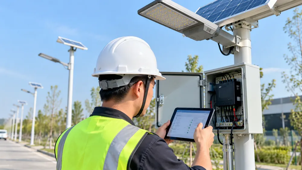
Cable routing inside the pole: run cables with service loops at the top (near the solar panel junction box) and at the base (near the controller enclosure). A service loop is 300–500mm of extra cable coiled inside the pole, secured with a cable tie. This allows you to remove the controller or panel junction box for servicing without pulling new cable. Without service loops, removing a module for repair requires either cutting the cable (and splicing it back) or removing the pole from the foundation. Both options cost $200–600 in labor and downtime.
Environmental sensor placement: if the pole includes temperature or humidity sensors (for environmental monitoring or adaptive dimming algorithms), mount them on the north side of the pole (in the Northern Hemisphere) or the south side (in the Southern Hemisphere) to avoid direct sunlight. Sensors in direct sunlight read 5–10°C higher than ambient temperature, which corrupts the data. Ensure the sensor has air circulation — don't mount it flush against the pole surface or inside a sealed enclosure. Use a sensor housing with a radiation shield (a white, ventilated cover) if the sensor will be exposed to sunlight during part of the day.
Why sensor misalignment discovered after installation is expensive: if a motion sensor doesn't trigger correctly, or a camera is pointed at the wrong area, the pole has to be re-accessed. For poles 4 meters and shorter, this means ladder work — $100–200 in labor. For poles taller than 4 meters, most sites require a bucket truck or scissor lift — $400–800 per day rental, plus two-person crew time. If the problem isn't discovered until after the installation crew has left the site, you're paying mobilization costs to bring them back. Plan sensor and camera alignment during installation, not after.
Factory pre-configuration vs. field configuration: some IoT parameters (network credentials, device ID, reporting interval) can be set at the factory before shipment. Others (GPS coordinates, sensor calibration, local time zone) must be set on-site. Clarify with the supplier which parameters require field configuration, and ensure the installation crew has the necessary tools (laptop or smartphone with configuration app, network credentials, access to the IoT platform). If the crew shows up without this information, the pole gets installed but the IoT features don't work — and that's a callback.
Vertical Alignment and Tilt Prevention
Plumb verification is the last structural checkpoint before the concrete cures. After that, the pole's position is permanent. A pole that's 1° out of plumb leans 17mm per meter of height — a 6-meter pole will be 102mm (4 inches) out of vertical at the top. That's visible to the eye, and it creates uneven loading that accelerates every other failure mode.
Use a 4-foot level (1.2 meter) on two perpendicular faces of the pole — north-south and east-west. A shorter level (2-foot or less) doesn't average out surface irregularities on the pole, so small bumps or welds can throw off the reading. Place the level against a flat section of the pole, not over a weld bead or mounting bracket. Check both axes because the pole can be plumb in one direction and off in the other.
Acceptable tolerance: ≤0.5° from vertical. In practical terms, that's about 1mm of deviation per meter of height when measured with a level. If the bubble in your level is centered, you're within tolerance. If it's one graduation off-center, measure the deviation at the top of the pole — if it exceeds 0.5° (roughly 9mm per meter), adjust before the concrete sets.
Shim placement under the base flange: if the pole is slightly out of plumb and the concrete is still wet, the cleanest fix is to add shims under the base flange on the low side. Use stainless steel or galvanized steel shims (not wood — wood compresses and rots). Stack shims to the required thickness, slide them under the flange, and recheck plumb. If the concrete has already started to set and you can't reposition the pole, you have two options: break out the concrete and re-pour (expensive, time-consuming), or accept the tilt and document it (not recommended for smart poles, where even small tilt affects sensor alignment).
When to re-level the foundation instead of shimming: if the pole is more than 2° out of plumb, the foundation is likely uneven or undersized. Shimming won't fix this — the shims will compress under load or the pole will continue to settle. Break out the concrete, inspect the excavation for soft spots or voids, re-compact the soil, and re-pour. This is a $500–1,000 mistake if discovered after the concrete cures, but it's a $50 fix if caught during the pour.
Concrete cure time before releasing temporary bracing: minimum 72 hours for standard concrete mix (3000 PSI/20 MPa) at 20°C ambient temperature. Cure time increases in cold weather — below 10°C, allow 96 hours or use accelerated concrete mix. Do not remove temporary bracing early to save time. The pole looks stable, but the concrete hasn't reached full strength, and wind load during curing can tilt the pole or crack the foundation.
Temporary bracing methods: for poles up to 6 meters, 2×4 lumber braces nailed to stakes driven into the ground at 120° intervals around the pole work for most sites. For poles over 6 meters, use adjustable pole jacks or guy wires anchored to stakes 3–4 meters from the pole base. Guy wires should be under light tension (just tight enough to prevent sway), not cranked tight — over-tensioning can pull the pole out of plumb.
Backfill compaction for direct-burial poles: if you're using direct burial (pole set in a hole with compacted aggregate backfill instead of concrete), compact in 150mm lifts with a plate compactor. Each lift should be at 95% of maximum dry density (determined by a Proctor test, but in the field, that means the aggregate is firm underfoot and doesn't shift when you walk on it). Moisture content matters — too dry and the aggregate won't compact, too wet and it acts like a slurry. Target moisture is 8–12% by weight (the aggregate should feel damp but not dripping when squeezed in your hand).
Wind loading during cure: if you're installing in an exposed site (coastal, hilltop, open field) and the weather forecast shows wind speeds over 40 km/h during the cure period, add temporary guy-wire anchoring for poles over 6 meters. Wind load on an uncured pole can tilt it before the concrete sets, and you won't know until the bracing comes off three days later. Guy wires cost $20 in materials and 15 minutes of labor — fixing a tilted pole costs $500–1,200.
Post-installation monitoring: 30-day and 90-day tilt checks catch foundation settlement before warranty claims arise. Use the same 4-foot level in the same locations (mark the level placement points on the pole with a paint pen during installation). If the pole has shifted more than 0.5° in 30 days, the foundation is settling — investigate the soil conditions and consider adding grade beams or helical piers to stabilize it. If you wait until 6 months or a year, the tilt is severe and the only fix is pole replacement.
Electrical Connection and System Commissioning
The electrical connections are the last step before the system goes live. This is where reverse polarity, loose connections, or incorrect controller programming turn into destroyed electronics or non-functional lighting. Each connection has a failure mode, and each failure mode has a specific prevention step.
Battery connection polarity verification: before connecting the battery to the charge controller, verify polarity with a multimeter. Red lead to positive terminal, black lead to negative terminal — the meter should read the battery voltage (12.0–12.8V for a fully charged 12V battery, 25.0–25.6V for a 24V battery). If the meter reads negative voltage, your polarity is reversed. Reverse polarity destroys the MPPT circuit in the charge controller — most controllers have reverse-polarity protection, but it's a fuse or sacrificial diode that blows to protect the upstream circuitry. Replacing the fuse costs 15 minutes; replacing the controller costs $80–150 and a return trip to the site.
Connect the battery to the controller before connecting the solar panel. The controller uses the battery voltage as a reference to determine system voltage (12V or 24V). If you connect the panel first, the controller sees the panel's open-circuit voltage (18–22V for a 12V panel, 36–44V for a 24V panel) and may misidentify the system voltage, which corrupts the charge algorithm.
Load (LED) connection and initial resistance check: connect the LED load to the controller's load terminals. Verify polarity (red to positive, black to negative). Before applying power, measure the resistance across the load terminals with a multimeter set to ohms. A typical 20–50W LED fixture should read 3–12 ohms (depending on system voltage and LED power). If the meter reads zero ohms, the load is shorted — check for damaged wiring or a manufacturing defect in the fixture. If the meter reads infinite resistance (open circuit), the load connection is broken or the LED driver has failed.
Panel open-circuit voltage verification: before connecting the panel to the controller, measure the panel's open-circuit voltage (Voc) with a multimeter. The panel should be in full sunlight, with no shade on the cells. A 12V panel typically reads 18–22V Voc; a 24V panel reads 36–44V Voc. If the voltage is low (more than 2V below the rated Voc on the panel's label), the panel is shaded, damaged, or has a failed bypass diode. If the voltage is zero, check the wiring from the panel to the junction box — an open connection or blown fuse in the junction box prevents current flow.
Controller programming: charge parameters, discharge depth, dimming schedule, IoT reporting interval. Most smart solar charge controllers have default settings that work for standard battery types (sealed lead-acid or lithium iron phosphate) and typical lighting schedules (dusk-to-dawn or 8-hour dimming profile). If your project uses a non-standard battery chemistry, or requires a custom dimming schedule (dimming after midnight, motion-activated brightening, seasonal schedules), program the controller before energizing the system. Use the controller's configuration app (smartphone or PC) or the button interface on the controller housing. Document the settings in the commissioning checklist — if the controller fails and needs replacement, you'll need to reprogram the new unit with the same parameters.
Ground fault testing: use a megohmmeter (insulation resistance tester) to measure resistance between the system DC negative terminal and ground. The meter applies 500V or 1000V DC and measures leakage current. For a properly installed system, the resistance should exceed 1 megohm (1,000,000 ohms) in dry conditions. If the reading is below 1 megohm, there's a ground fault — water intrusion in a junction box, damaged cable insulation, or a pinched wire contacting the pole structure. Locate and repair the fault before energizing the system. Operating with a ground fault accelerates corrosion, drains the battery, and creates a shock hazard.
LED functional test: after the system is energized, verify LED operation at full brightness (night mode), dimming levels (if applicable), and motion-trigger response (if the fixture has a motion sensor). Cover the solar panel with an opaque cloth to simulate nighttime — the controller should detect low panel voltage and energize the load. Remove the cloth and confirm the LED turns off (or enters standby mode) when the panel voltage rises above the day/night threshold. If the LED doesn't turn on, check the load terminal connections and verify the controller's load output settings. If the LED is dim, check the battery voltage — a deeply discharged battery won't deliver full power until it's charged.
IoT connectivity verification: if the pole includes IoT modules (remote monitoring, dimming control, sensor data reporting), verify connectivity before leaving the site. Check that the module has transmitted its first data packet and that the packet appears on the IoT platform or cloud dashboard. Confirm the reported data (GPS coordinates, battery voltage, panel voltage, system status) matches the physical installation. If the module doesn't connect, check the antenna connection, network credentials (APN for cellular, network key for LoRaWAN), and signal strength (RSSI). An RSSI below -115 dBm indicates weak coverage — reposition the antenna or move to a higher mounting location.
Documentation for maintenance crew: before commissioning is complete, create a handover document that includes the controller access code (if the controller is password-protected), sensor calibration values, IoT network credentials, and any non-standard configuration settings. The maintenance crew may need to access the controller months or years after installation — if the password or network key isn't documented, they'll have to factory-reset the controller, which erases all custom settings. Store the handover document in a project folder accessible to the maintenance team, not just the installation crew.
Common Installation Mistakes That Cause Premature Failures
We track warranty claims and field failures across our customer base. Most failures aren't random — they cluster around specific installation practices that get repeated because "that's how we've always done it" or because the crew is under time pressure. Here are the mistakes that show up most often in failure reports.
Foundation undersizing: using a 4-meter pole foundation spec for a 6-meter pole because the excavation is already dug and the crew doesn't want to re-dig. The pole stands up initially, but within six months it tilts under wind load. The foundation doesn't have enough mass or embedment depth to counteract the overturning moment. This is a $1,500 mistake — the pole has to come down, the foundation has to be broken out, a new foundation has to be poured, and the pole has to be re-installed. The $50 saved on concrete costs $1,500 to fix.
Skipping the torque wrench: "tight enough" produces anchor bolts that are 30% outside the target torque range in field audits we've done with buyers. Over-torqued bolts stretch and creep, under-torqued bolts loosen. Both cause tilt. A torque wrench costs $60–120 depending on the range and accuracy. It pays for itself on the first pole where it prevents a tilt failure. If the crew doesn't have a torque wrench, rent one or delay the installation until one is available.
Ignoring galvanic series: steel bolts on aluminum panel frames, copper grounding wire attached directly to a galvanized steel pole, dissimilar metals in contact without isolation. Galvanic corrosion happens when two metals with different electrochemical potentials are in electrical contact in the presence of an electrolyte (moisture). The more anodic metal corrodes preferentially. Aluminum corrodes when in contact with steel. Galvanized steel corrodes when in contact with copper. The fix is simple — use stainless steel fasteners for aluminum components, use zinc-rich washers or dielectric isolators between dissimilar metals, and apply conductive grease to threads. The corrosion is invisible for the first 6–12 months, then suddenly the fasteners are green and the contact surfaces are pitted.
Cable gland over-tightening: tightening the cable gland "as tight as possible" crushes the cable jacket and creates a water ingress pathway inside the cable. Water migrates along the conductor strands (capillary action), reaches the junction box or controller enclosure, and corrodes the terminals. The gland looks sealed from the outside, but water is inside the cable. Use a torque wrench or torque screwdriver for cable glands — PG13.5 glands typically require 3–4 Nm, PG16 glands require 5–6 Nm. This is hand-tight with a small wrench, not impact-gun tight.
Panel azimuth "eyeballing": pointing the panel "toward the sun" without using a compass results in 15° azimuth errors in about 40% of installations we've audited. Fifteen degrees looks correct to the eye but costs 5–12% annual yield depending on latitude. The crew finishes the installation, the buyer accepts the poles, and the yield is below projection for the life of the system. Use a declination-corrected compass or a solar pathfinder — both cost less than $50 and eliminate the error.
Omitting service loops: routing cables tight from junction box to controller, with no slack. When the controller fails (and charge controllers do fail — they're the most-replaced component in a solar lighting system), the maintenance crew has to pull new cable because there isn't enough slack to remove the controller from its mounting location. Pulling cable inside a 6-meter pole requires removing the pole or fishing new cable from top to bottom, which costs $200–400 in labor. A 300mm service loop at each end costs nothing and makes every future maintenance task faster.
Concrete pour in freezing conditions: pouring concrete when the ambient temperature is below 5°C without using accelerated mix or insulating blankets. The concrete doesn't cure properly — it loses strength, develops microcracks, and the bond between the concrete and the anchor bolts is weak. The foundation fails under load within the first year. If the weather forecast shows freezing temperatures during the cure period, use cold-weather concrete mix (with accelerators) and cover the foundation with insulating blankets. If you can't meet those conditions, delay the pour.
Battery connection before panel isolation: connecting the battery to the controller while the solar panel is generating power. If the panel is in full sunlight, the controller sees inrush current from both the battery and the panel simultaneously, which can trip the controller's overcurrent protection or damage the MPPT circuit. Connect the battery first, verify the system is stable (controller display shows battery voltage), then connect the panel. The panel connection is the last electrical step, not the first.
Factory Support for Installation Planning and Custom Configurations
Most of the installation problems described in this guide come from mismatches between the pole configuration and the site conditions — soil type, wind zone, latitude, or IoT coverage requirements that weren't accounted for during ordering. We can't prevent installation errors from happening in the field, but we can prevent design errors from happening before the order ships.
JXSOL's engineering team reviews pole configurations during the pre-order phase for buyers who provide site data: target latitude, wind zone, soil type, and coverage requirements. We validate that the foundation spec matches the soil and wind loading, confirm the panel tilt angle is appropriate for the latitude, and verify that IoT antenna placement and connectivity are feasible given the site's network coverage. This doesn't cost extra — it's part of the standard RFQ process for orders over 100 units — but it requires buyers to send site data before ordering, not after installation when the problems show up.
Foundation design assistance: if your site has non-standard conditions (soft soil, high water table, coastal exposure, seismic zone), our engineering team can provide bolt load calculations and concrete mix recommendations. We work with buyers' local structural engineers to confirm the foundation meets local codes and loading requirements. Most suppliers send a pole and leave the buyer to figure out the foundation on-site. We've seen buyers over-design (spending $200 extra per pole on unnecessary foundation depth) or under-design (saving $50 per pole and paying $1,500 per pole to fix tilt failures). Foundation engineering is a $2,000 cost at the project level that prevents $50,000 in field failures at the deployment level.
Custom pole heights, arm lengths, and panel tilt brackets: OEM/ODM buyers who need site-specific configurations can order poles with custom dimensions. Standard catalog heights are 4m, 5m, 6m, and 8m, but we produce intermediate heights (4.5m, 5.5m, 7m) and custom arm lengths for buyers who need specific coverage patterns. Panel tilt brackets can be factory-set to any angle between 10° and 60°, or supplied with adjustable brackets for field tuning. Custom configurations add 7–10 days to production time and require a 100-unit minimum order, but they eliminate field modifications and ensure the pole matches the site requirements on arrival.
Factory QC on structural components: fasteners, housings, waterproof joints, and gasket seating are inspected before shipment. Buyers working with sourcing agents or distributors often receive poles where the base flange is scratched during shipping, the cable glands are missing lock washers, or the anchor bolt threads are damaged. These are small problems that become field failures — the scratched flange corrodes at the damage point, the cable gland leaks, the anchor bolt can't be torqued to spec. Our QC process catches these before the pole leaves the factory, which reduces field failure risk compared to supply chains where the factory never sees the final assembly.
Installation documentation package: for orders over 200 units, we provide torque specs, wiring diagrams, and commissioning checklists in the buyer's target language (English, Spanish, French, Arabic depending on the export market). Most manufacturers provide documentation in Chinese or generic English. If the installation crew is local labor in the destination country, they need documentation in their working language. Translation costs $300–500 per project but prevents miscommunication that leads to installation errors.
Post-installation technical support: troubleshooting connectivity issues, sensor calibration, firmware updates. IoT modules occasionally need firmware updates to fix bugs or add features. If the supplier is a sourcing agent or distributor, they can't provide firmware files or remote troubleshooting — they don't have engineering access to the product. As the manufacturer, we maintain firmware and calibration tools for the life of the product. If a buyer has a connectivity problem six months after installation, our engineering team can remote-access the IoT platform and diagnose the issue. This matters for large deployments (500+ poles) where on-site troubleshooting isn't economically feasible for every individual pole.
Why working with the manufacturer vs. a distributor for first deployment: engineering access during planning prevents costly redesigns after ordering. Distributors and sourcing agents are commercial intermediaries — they can process orders and handle logistics, but they can't answer engineering questions or validate configurations. For a buyer's first smart solar pole deployment, engineering support during planning is worth more than price arbitrage. Once you've validated the configuration and installation process on the first project, reorders through distributors make sense. But the first deployment is where mistakes get locked in, and having engineering access before ordering prevents those mistakes.